

Computational fluid dynamics analysis of blade tip clearances on hemodynamic performance and blood damage in a centrifugal ventricular assist device
- PMID: 19832736
- PMCID: PMC3030194
- DOI: 10.1111/j.1525-1594.2009.00875.x
Computational fluid dynamics analysis of blade tip clearances on hemodynamic performance and blood damage in a centrifugal ventricular assist device
Abstract
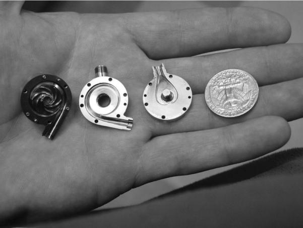
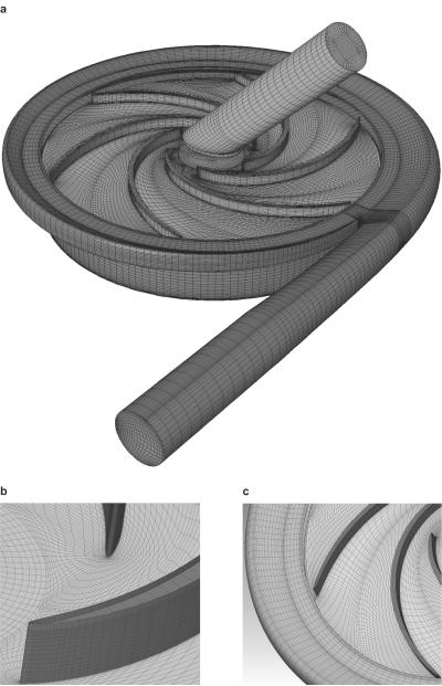
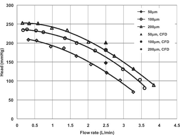
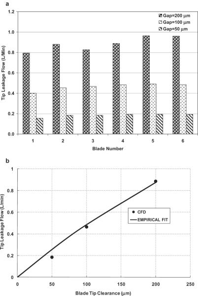
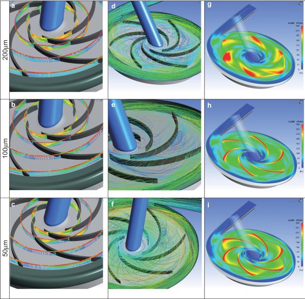
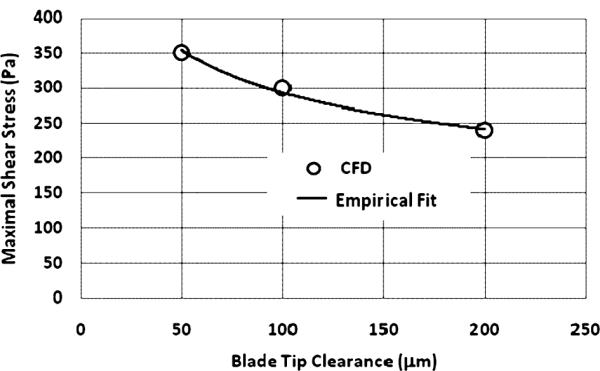
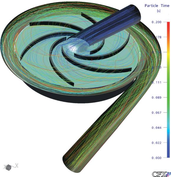
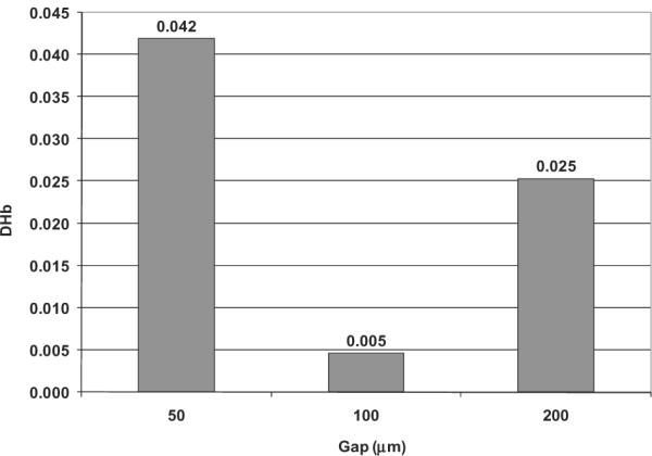
An important challenge facing the design of turbodynamic ventricular assist devices (VADs) intended for long-term support is the optimization of the flow path geometry to maximize hydraulic performance while minimizing shear-stress-induced hemolysis and thrombosis. For unshrouded centrifugal, mixed-flow and axial-flow blood pumps, the complex flow patterns within the blade tip clearance between the lengthwise upper surface of the rotating impeller blades and the stationary pump housing have a dramatic effect on both the hydrodynamic performance and the blood damage production. Detailed computational fluid dynamics (CFD) analyses were performed in this study to investigate such flow behavior in blade tip clearance region for a centrifugal blood pump representing a scaled-up version of a prototype pediatric VAD. Nominal flow conditions were analyzed at a flow rate of 2.5 L/min and rotor speed of 3000 rpm with three blade tip clearances of 50, 100, and 200 microm. CFD simulations predicted a decrease in the averaged tip leakage flow rate and an increase in pump head and axial thrust with decreasing blade tip clearances from 200 to 50 microm. The predicted hemolysis, however, exhibited a unimodal relationship, having a minimum at 100 microm compared to 50 microm and 200 microm. Experimental data corroborate these predictions. Detailed flow patterns observed in this study revealed interesting fluid dynamic features associated with the blade tip clearances, such as the generation and dissipation of tip leakage vortex and its interaction with the primary flow in the blade-blade passages. Quantitative calculations suggested the existence of an optimal blade tip clearance by which hydraulic efficiency can be maximized and hemolysis minimized.
Figures


References
-
- Goto A. Study of internal flows in a mixed-flow pump impeller at various tip clearances using three-dimensional viscous flow computations. ASME J Turbomach. 1992;114:373–82.
-
- Engeda A, Rautenberg M. Comparison of the relative effect of tip clearance on centrifugal impellers. ASME J Turbomach. 1987;109:545–9.
-
- Hirsch C, Kang S, Pointel GA. Numerically supported investigation of the 3-d flow in centrifugal impellers, Part II: secondary flow structure. ASME Paper. 1996:96-GT–152.
-
- Antaki JF, Ghattas O, Burgreen GW, He B. Computational flow optimization of rotary blood pump components. Artif Organs. 1995;19:608–15. - PubMed
-
- Wu J, Antaki JF, Wagner W, Snyder T, Paden B, Borovetz H. Elimination of adverse leakage flow in a miniature pediatric centrifugal blood pump by computational fluid dynamics-based design optimization. ASAIO J. 2005;51:636–43. - PubMed
Publication types
MeSH terms
Grants and funding
LinkOut - more resources
Full Text Sources
Miscellaneous
