. 2009 Nov 10;106(45):18966-71.
doi: 10.1073/pnas.0907941106. Epub 2009 Oct 27.

Structure of the lethal phage pinhole

Affiliations

Structure of the lethal phage pinhole

Ting Pang et al. Proc Natl Acad Sci U S A. .

Abstract

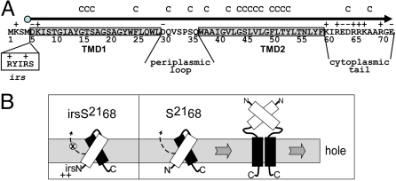
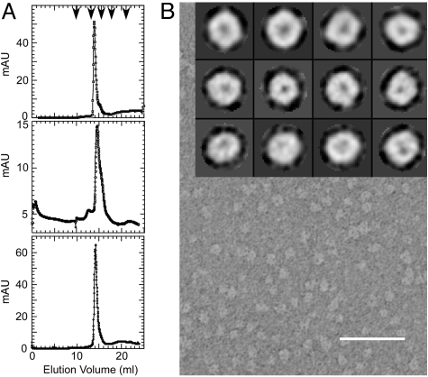
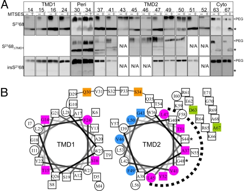
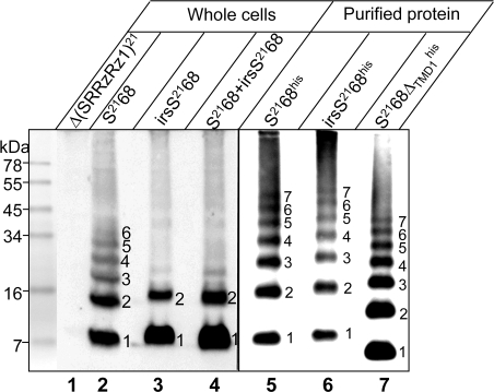
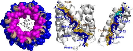
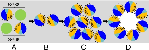
Perhaps the simplest of biological timing systems, bacteriophage holins accumulate during the phage morphogenesis period and then trigger to permeabilize the cytoplasmic membrane with lethal holes; thus, terminating the infection cycle. Canonical holins form very large holes that allow nonspecific release of fully-folded proteins, but a recently discovered class of holins, the pinholins, make much smaller holes, or pinholes, that serve only to depolarize the membrane. Here, we interrogate the structure of the prototype pinholin by negative-stain transmission electron-microscopy, cysteine-accessibility, and chemical cross-linking, as well as by computational approaches. Together, the results suggest that the pinholin forms symmetric heptameric structures with the hydrophilic surface of one transmembrane domain lining the surface of a central channel approximately 15 A in diameter. The structural model also suggests a rationale for the prehole state of the pinholin, the persistence of which defines the duration of the viral latent period, and for the sensitivity of the holin timing system to the energized state of the membrane.


Conflict of interest statement

The authors declare no conflict of interest.

Figures

Fig. 1.
Fig. 1.
Features of S2168. (A) Sequence of the S21 reading frame. The 71 residues encoded by the S21 gene are shown, with the S2168 reading frame, which begins with Met4, depicted by the arrowhead line. TMD1 and TMD2 are indicated by shaded boxes, and the regions corresponding to the periplasmic loop and cytoplasmic tail are so labeled. Residues altered to Cys for this study are indicated by C above the sequence. The irs epitope inserted after Met-4 in the irsS2168 variant is shown in the clear box. (B) Model for pinhole formation by S2168. TMD1 (white) is initially in the membrane, bound to TMD2 (black). When TMD1 exits the membrane, TMD2 is able to dimerize and then oligomerize, in the pathway to pinhole formation. TMD1 undergoes homotypic interactions in the periplasm that facilitate, but are not necessary, for pinhole formation. To the left, the inhibitory effect of the irs epitope, with its two positive charges, on the release of TMD1 from the membrane is depicted. Modified from Park et al. (7) with permission.
Fig. 2.
Fig. 2.
In vitro characterization of his-tagged S2168 and its derivatives. (A) Gel filtration of S2168his and derivatives. Purified protein was applied to a Superdex 200 column and analyzed as described in Materials and Methods. (Top) S2168his; (Middle) S2168ΔTMD1his; (Bottom) irsS2168his. Arrowheads indicate the protein standards, from left to right: 670, 158, 44, 17, and 1.35 kDa. (B) Electron micrograph of negatively stained S2168his purified in DDM. (Scale bar, 500 Å.) (Inset) Single particle averages for S2168his (top row), S2168ΔTMD1his (middle row), and irsS2168his (bottom row). Each single box is 148 × 148 Å.
Fig. 3.
Fig. 3.
MTSES protection analysis of S2168. (A) Whole cells carrying plasmids encoding single-Cys substitutions of S2168 or its derivatives were induced, treated with the nonpermeant thiol reagent MTSES, subjected to organic denaturation and delipidation, treated with PEG-maleimide, and analyzed by immunoblot, as described in Materials and Methods. The asterisk and “+PEG” indicate the position of the unmodified monomer and the PEGylated species, respectively. MTSES protection is indicated by an MTSES-dependent decrease in the PEGylated species and increase in the unmodified species. NA, not available; Peri, periplasmic loop; Cyto, cytoplasmic tail. (B) MTSES-protected positions in TMD2 map to its most hydrophilic face. Helical projections of TMD1 and TMD2 are shown, with hydrophobic residues as circles and hydroxylated, and hydrophilic residues, as well as Ala and Gly, as squares. Magenta and blue indicate transmembrane positions of S2168 that do or do not show protection by MTSES. Also shown are the positions in the periplasmic loop (orange) and cytoplasmic tail (green) that show MTSES protection. The dashed arc indicates the deduced luminal face of TMD2. Asterisks, GxxxSxxxG motif in TMD2.
Fig. 4.
Fig. 4.
DSP cross-linking reveals pinholin oligomerization in vivo and in vitro. (Left) Whole cells carrying prophage λQ21Δ(SRRzRz1)21 only (lane 1), or prophage λQ21Δ(SRRzRz1)21 with either plasmid pS2168 (lane 2), pirsS2168* (lane 3), or prophage λS2168 with the plasmid pirsS2168* (lane 4), as indicated, were induced, treated with the cross-linker DSP, and analyzed by SDS/PAGE and immunoblot, as described in Materials and Methods. (Right) Protein purified from expression of alleles encoding his-tagged S2168 or its derivatives, as indicated, was treated with DSP and analyzed by immunoblot. Oligomeric state indicated for each cross-linked species.
Fig. 5.
Fig. 5.
Computational model for the heptameric pinhole. (Left) Top down view of n = 7 pinhole model with pore distances shown at various depths. MTSES- sensitive and insensitive positions are shown in magenta and blue, respectively. (Center) Side view of n = 7 pinhole model showing the helix–helix interaction contact surface. Contact surface A containing the glycine zipper is shown in gold and labeled in brown; the Gly40, Ser44, and Gly48 contact surface is colored brown. Contact surface B is shown and labeled in blue. (Right) A luminal view of the contact surface, with five helices removed for clarity. Contact surfaces are colored as in Center, except that Val41 is shown in cyan.
Fig. 6.
Fig. 6.
Model for the pinhole formation pathway. View is top-down from periplasm; gray, lipid. TMD1 and TMD2 are shown as green and sectored circles, respectively. In TMD2, orange and dark blue represent A and B interaction faces (Fig. 5), with 0, 4, and 8 indicating the helical positions of the G40, S44, and G48 residues, respectively. The face accessible to MTSES in the pinhole is indicated by the dashed arc. (A) Inactive dimers, with bracket linking cognate TMD1 and TMD2; one possible orientation is shown. (B) Active dimers, after escape of TMD1 from membrane; homotypic interface. (C) Aggregate of active dimers; actual number of dimers is likely to be much larger. (D) Heptameric pinholes after triggering; heterotypic interface.

References

    1. Young R, Wang IN. Phage Lysis. In: Calendar R, editor. The Bacteriophages. 2nd Ed. Oxford: Oxford Univ Press; pp. 104–126.
    1. Berry J, Summer EJ, Struck DK, Young R. The final step in the phage infection cycle: The Rz and Rz1 lysis proteins link the inner and outer membranes. Mol Microbiol. 2008;70:341–351. - PMC - PubMed
    1. Young R. Bacteriophage holins: Deadly diversity. J Mol Microbiol Biotechnol. 2002;4:21–36. - PubMed
    1. Bläsi U, Young R. Two beginnings for a single purpose: The dual-start holins in the regulation of phage lysis. Mol Microbiol. 1996;21:675–682. - PubMed
    1. Wang IN, Deaton J, Young R. Sizing the holin lesion with an endolysin-beta-galactosidase fusion. J Bacteriol. 2003;185:779–787. - PMC - PubMed

Publication types

LinkOut - more resources