. 2009 Nov 1;9(6):318-33.

Cardiac conduction system: delineation of anatomic landmarks with multidetector CT

Affiliations

Cardiac conduction system: delineation of anatomic landmarks with multidetector CT

Farhood Saremi et al. Indian Pacing Electrophysiol J. .

Abstract

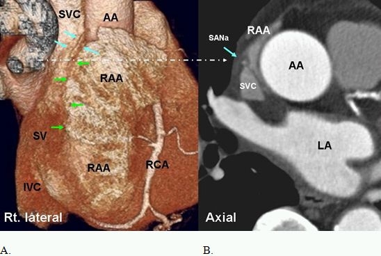
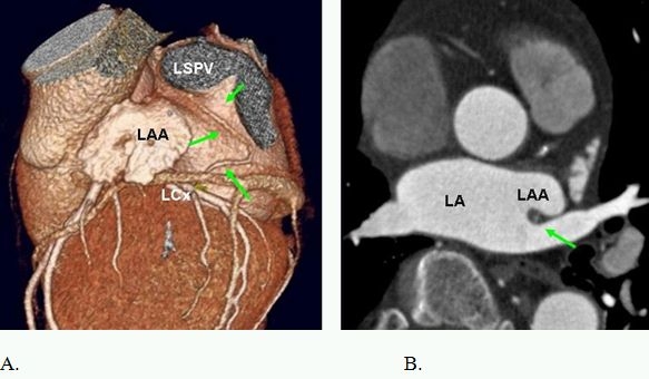
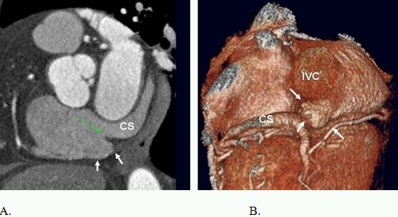
Major components of the cardiac conduction system including the sinoatrial node (SAN), atrioventricular node (AVN), the His Bundle, and the right and left bundle branches are too small to be directly visualized by multidetector CT (MDCT) given the limited spatial resolution of current scanners. However, the related anatomic landmarks and variants of this system a well as the areas with special interest to electrophysiologists can be reliably demonstrated by MDCT. Some of these structures and landmarks include the right SAN artery, right atrial cavotricuspid isthmus, Koch triangle, AVN artery, interatrial muscle bundles, and pulmonary veins. In addition, MDCT has an imperative role in demarcating potential arrhythmogenic structures. The aim of this review will be to assess the extent at which MDCT can outline the described anatomic landmarks and therefore provide crucial information used in clinical practice.

Keywords: Cardiac Conduction System; Delineation of Anatomic Landmarks; Multidetector CT.


Figures

Figure 1
Figure 1
A. Right lateral volume rendered image of the heart shows the terminal segment of SA node artery (SANa) (blue arrows) in the sulcus terminalis (green arrow). Large right atrial appendage (RAA) with irregular surface due to prominent pectinate muscles is seen. B. Axial view at the approximate level of the SA node (long arrow) demonstrates central position of the SANa (blue arrow) within the crista terminalis at superior cavoatrial junction. The SA node is arranged around the SANa. AA=ascending aorta, LA=left atrium, RCA=right coronary artery, IVC=inferior vena cava, SV=sinus venarum
Figure 2
Figure 2
Anatomy of the interatrial septum and patent foramen ovale (PFO). Short axis (SAX) images perpendicular to the interatrial septum show the fossa ovale (FO) in (A) and a well structured PFO in (B). The septum primum (black arrows in B) is fused to the inferior rim of fossa ovale (FO) and extends superiorly as a flap. The superior and the inferior rims (white arrows) of the FO are formed by infolding of the right atrial wall [interatrial groove (IAG) or the septum secundum]. IAG (double headed arrows) contains extracardiac fat. The infolding of the right atrial wall overlaps the flap of septum primum, forming a narrow tunnel through which a probe can be passed (51). AA= ascending aorta, LA=left atrium, RA=right atrium, S=superior, I=inferior. Reproduced from: Saremi F, Tafti M. The role of computed tomography and magnetic resonance imaging in ablation procedures for treatment of atrial fibrillation. Semin Ultrasound CT MR. 2009;30:125-56, Copyright (2009), with permission from Elsevier.
Figure 3
Figure 3
Short axis images at the level of fossa ovalis demonstrate different anatomic variants. A. PFO with small left to right shunt (arrow). B. flap valve closed at the point of entry into the right atrium. This variant is seen in 15% of individuals. C. Incompetent valves with free flow of contrast from left to right (arrow). Note, the flap valve is too short causing valve incompetency. D. Atrial septal aneurysm. LA=left atrium, RA=right atrium.
Figure 4
Figure 4
Axial images in two different patients. A. demonstrates the arterial supply of the sinoatrial node artery (SANa) arising from the proximal right coronary artery (RCA). Terminal segment of the SANa passes behind the superior vena cava (SVC) (retrocaval). Retrocaval course occurs in 47% of individuals. B. The terminal portion of the SANa is not seen. However enhancing SA node (SAN) (small arrows) can be seen in epicardial aspect of the crista terminalis (CT). CT is partially infiltrated by fat. AA=ascending aorta.
Figure 5
Figure 5
Short axis images in two different patients demonstrate the crista terminalis (red arrows) as a dark band between right atrial appendage (RAA) and sinus venarum (SV) extending from the superior vena cava (SVC) to the inferior vena cava (IVC). Superiorly, the CT arches anterior to the orifice of the SVC and extends to the area of the anterior interatrial groove and merges with the interatrial bundle, commonly known as Bachmann's bundle (green arrows). Prominent pectinate muscles (PM) are seen. LA=left atrium, AA=ascending aorta.
Figure 6
Figure 6
Anatomic course of the S-shaped SAN artery. A. Arising from the proximal left circumflex artery (LCx), it turns posteriorly and moves in the groove between the left atrial appendage (LAA) and the left superior pulmonary vein (LSPV) orifices (short arrows). 30% of SAN arteries arising from the LCX are S-shaped in their anatomic course.
Figure 7
Figure 7
A. B., and C. Inferior pyramidal space (dotted triangle) is the anatomic location of atrioventricular node artery (AVNa). The AVNa originates from the distal right coronary artery (RCA) and penetrates into the base of the posterior interatrial septum. The AVNa supplies the AV node at the apex of the pyramid, in close proximity to the muscular atrioventricular septum. This area is not a true septum but extracardiac fat sandwiched between the right atrium (RA) and the left atrium (LV) (arrow in c). The septal isthmus (SI) is shown in (C) extending between the septal tricuspid valve (STV) and coronary sinus ostium. The AVNa is in potential danger when ablation procedure of the septal isthmus is performed. SAX=short axis view, 2ch= two chamber view, 4ch=four chamber view, LV= left ventricle. SI=septal isthmus (bracket).
Figure 8
Figure 8
Variants of Bachman bundle (BB) and CS-LA muscle continuity. A. BB is shown (black arrow) connecting the two atria anteriorly up to the junction of the superior vena cava (SVC) in the right atrium (RA) and extending to the left atrial appendage (LAA) in the left atrium. B. Shows complete replacement of BB by fat (within the circle). C. Proximal CS-LA attachment (black arrow) near the junction with the great cardiac vein. D. No CS-LA attachment. Fat fills the space between the CS and left atrial wall. CS=coronary sinus, LA=left atrium.
Figure 9
Figure 9
3D posterior views of the heart. The length of the CTI varies in different individuals (upper panel, different patients) and different cardiac phases (lower panel, same patient). Knowledge of these anatomic variants prior to catheter ablation for atrial flutter will save time and increases the success rate.
Figure 10
Figure 10
Short axis (A) and volume rendered (B) images show a large subthebesian pouch (white arrows) extending beneath the coronary sinus (CS) orifice and the Thebesian valve (green arrow).
Figure 11
Figure 11
Anatomic variants of the pulmonary vein insertion. It is not uncommon to see mild narrowing of the left inferior pulmonary vein (LIPV) at its confluence with the left atrium. This is most likely secondary to the compressive effect of the pulsating aorta and should not be mistaken for stenosis after radiofrequency ablations. Medial insertion of the LIPV is relatively rare and may cause difficulty for circumferential pulmonary vein isolation. Common ostium is common and can happen on either left or right side. Early branching is also common and usually is seen with right upper lobe pulmonary vein entering near the confluence of right superior pulmonary vein with the left atrium.
Figure 12
Figure 12
A. Oblique vein of Marshall (green arrow) versus B. persistent left superior vena cava (red arrow). CS=coronary sinus, GCV=great cardiac vein.
Figure 13
Figure 13
Parasympathetic ganglionic plexi of the heart (within the circles). It is difficult to image vagus plexi of the heart. However, those can indirectly be localized by enhancement of their rich vascular supply. Multiple ganglia exist. The largest collection are located in the fad pad of superior (A) and inferior cavo-atrial junctions (B). Surgical or catheter ablation of these structures have been used for successful ablation of atrial fibrillation. CS=coronary sinus, RA=right atrium, LA=left atrium, IVC=inferior vena cava.

Similar articles

Cited by

References

    1. Sanchez-Quintana D, et al. Anatomy of cardiac nodes and atrioventricular specialized conduction system. Rev Esp Cardiol. 2003;56:1085. - PubMed
    1. Malouf JF, et al. Functional anatomy of the heart. In: Fuster V, et al., editors. The heart. 11th ed. New York, NY: McGraw-Hill; 2004. p. 75.
    1. Ho SY, et al. Atrial structure and fibres: morphologic bases of atrial conduction. Cardiovasc Res. 2002;54:325. - PubMed
    1. Anderson RH, et al. The anatomy of the heart revisited. Anat Rec. 1996;246:1. - PubMed
    1. Edwards WD. Applied anatomy of the heart. In: Giuliani ER, et al., editors. Cardiology: fundamentals and practice, 2nd ed. St. Louis: St. Louis; 1991. p. 47 .

LinkOut - more resources