. 2009 Sep 28;17(20):17555-62.
doi: 10.1364/OE.17.017555.

Optofluidic generation of Laguerre-Gaussian beams

Affiliations

Optofluidic generation of Laguerre-Gaussian beams

Gavin D M Jeffries et al. Opt Express. .

Abstract

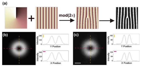
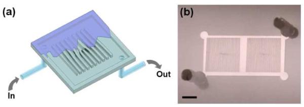
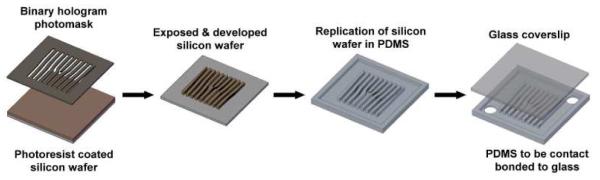
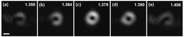
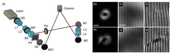
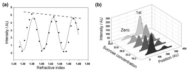
Laguerre-Gaussian (LG) beams have been extensively studied due to their unique structure, characterized by a phase singularity at the center of the beam. Common methods for generating such beams include the use of diffractive optical elements and spatial light modulators, which although offering excellent versatility, suffers from several drawbacks, including in many cases a low power damage threshold as well as complexity and expense. This paper presents a simple, low cost method for the generation of high-fidelity LG beams using rapid prototyping techniques. Our approach is based on a fluidic-hologram concept, whereby the properties of the LG beam can be finely controlled by varying the refractive-index of the fluid that flows through the hologram. This simple approach, while optimized here for LG beam generation, is also expected to find applications in the production of tunable fluidic optical trains.


Figures

Fig. 1
Fig. 1
Generation of LG01 beams. (a) Illustration showing the generation of the binary hologram pattern, by combining the spiral phase profile with a blaze kinoform then binarizing the result through thresholding. (b) Theoretical output of the first diffracted-order mode. (c) Experimental measurement of the first diffracted-order mode. Insets in (b) and (c) show the line profiles through the center of the beam. The scale bar in (c) represents 1mm.
Fig. 2
Fig. 2
Schematic illustration and image of the constructed fluidic-hologram device. (a) A 3D rendering of the device, showing fluidic input-output ports. (b) A photograph of two fully assembled fluidic holograms bonded to a glass coverslip, with access ports punched for the two holograms. The scale bar in the image represents 2 mm.
Fig. 3
Fig. 3
Outline of the fabrication procedure to form a fluidic hologram, illustrating the key stages. The silicon wafer is coated with a negative photoresist, exposed to UV through the photomask, then developed forming a master. This master is fluorosilane treated and a PDMS cast is made. Port holes are punched into the PDMS cast for tubing and then bonded to a glass coverslip using an oxygen plasma treatment.
Fig. 4
Fig. 4
Five examples of experimental measurements of the first diffraction-order beam generated from a single fluidic hologram, with a varied refractive index solution content, taken at a propagation distance of 0.7m. Panels (a) to (e) show the generated modes with path-length differences from less than λ/2 to greater than λ/2, created by varying the sucrose concentration. Each panel is noted with the refractive-index of the medium contained within the fluidic hologram. These beam profile were measured using the setup displayed in Fig. 5(a). The scale bar in (a) represents 1mm.
Fig. 5
Fig. 5
Interference images of the generated modes with a plane wave. The left panel (a) shows a schematic of the setup to generate the interference on a camera, with a propagation distance from hologram to camera of 2.5m. M1, M2 are mirrors, L1-L2 and L3-L4 are telescoping lens pairs, Pol is a polarizer, BS is a polarizing beam splitter, WP is a half-wave plate, ND is a neutral density filter, FH is the fluidic hologram, and M/C is a mirror in the interference setup or the beam profile camera in the setup used to image the modes in Fig. 4. Panels (b) & (e) are mode images taken on the CCD camera. (c) & (f) are raw interference images of the LG mode interfered with an expanded Gaussian beam. (d) & (g) are threshold images of (c) & (f) to illustrate the characteristic fork structure. The pattern in (d) matches the binary mask used to generate the fluidic hologram, suggesting the resulting mode has an l index of 1. The scale bar in (b) represents 4mm, (b) and (e) are scaled the same. The scale bar in (c) represents 0.5mm, (c-d) and (f-g) are all scaled the same.
Fig. 6
Fig. 6
Changes in intensity as a function of refractive-index. (a) A plot of the first-order intensity versus the solution refractive-index, exhibiting a sinusoidal variation. The solid trend line illustrates a refractive-index periodicity of 0.043. The dashed trend line indicates an overall power attenuation, suggesting an increase in absorption/scatter of the illuminating light as the sucrose concentration is increased. (b) A comparison plot illustrating the inversely proportional response of the zeroth and first-order diffraction modes, from a linear fluidic grating of the same periodicity as the blazing function used in our fluidic hologram. Intensities were measured from linescans of mode images taken across the polarization axis.

Similar articles

References

    1. Allen L, Beijersbergen MW, Spreeuw RJC, Woerdman JP. Orbital angular momentum of light and the transformation of Laguerre-Gaussian laser modes. Phys. Rev. A. 1992;45(11):8185–8189. - PubMed
    1. Parkin SJ, Knöner G, Nieminen TA, Heckenberg NR, Rubinsztein-Dunlop H. Picoliter viscometry using optically rotated particles. Phys. Rev. E Stat. Nonlin. Soft Matter Phys. 2007;76(4):041507. - PubMed
    1. Leach J, Mushfique H, di Leonardo R, Padgett M, Cooper J. An optically driven pump for microfluidics. Lab Chip. 2006;6(6):735–739. - PubMed
    1. Ladavac K, Grier DG. Microoptomechanical pumps assembled and driven by holographic optical vortex arrays. Opt. Express. 2004;12(6):1144–1149. - PubMed
    1. Neale SL, MacDonald MP, Dholakia K, Krauss TF. All-optical control of microfluidic components using form birefringence. Nat. Mater. 2005;4(7):530–533. - PubMed

Publication types