. 2009 Nov 18;97(10):2664-73.
doi: 10.1016/j.bpj.2009.08.036.

Organization of ryanodine receptors, transverse tubules, and sodium-calcium exchanger in rat myocytes

Affiliations

Organization of ryanodine receptors, transverse tubules, and sodium-calcium exchanger in rat myocytes

Izzy Jayasinghe et al. Biophys J. .

Abstract

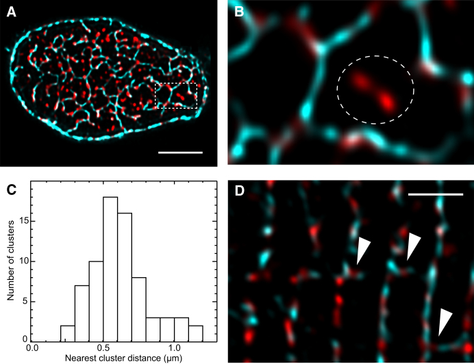
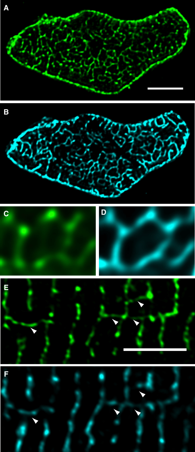
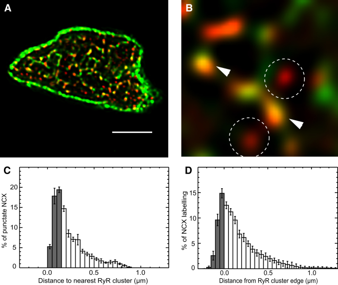
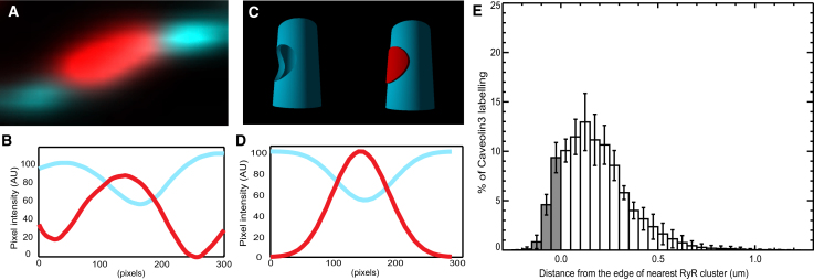
Confocal and total internal reflection fluorescence imaging was used to examine the distribution of caveolin-3, sodium-calcium exchange (NCX) and ryanodine receptors (RyRs) in rat ventricular myocytes. Transverse and longitudinal optical sectioning shows that NCX is distributed widely along the transverse and longitudinal tubular system (t-system). The NCX labeling consisted of both punctate and distributed components, which partially colocalize with RyRs (27%). Surface membrane labeling showed a similar pattern but the fraction of RyR clusters containing NCX label was decreased and no nonpunctate labeling was observed. Sixteen percent of RyRs were not colocalized with the t-system and 1.6% of RyRs were found on longitudinal elements of the t-system. The surface distribution of RyR labeling was not generally consistent with circular patches of RyRs. This suggests that previous estimates for the number of RyRs in a junction (based on circular close-packed arrays) need to be revised. The observed distribution of caveolin-3 labeling was consistent with its exclusion from RyR clusters. Distance maps for all colocalization pairs were calculated to give the distance between centroids of punctate labeling and edges for distributed components. The possible roles for punctate NCX labeling are discussed.


Figures

Figure 1
Figure 1
T-tubular architecture in fixed myocytes. (A) Longitudinal confocal sectioning through a CAV3-labeled myocyte shows transverse rows of Z-line-associated t-tubules throughout the interior of the cell. Longitudinal tubules were frequently observed (arrows) and often are aligned along 3–4 sarcomeres. (B) Shallow maximum intensity projection in a cell orientated vertically and imaged in transverse confocal sections (x-y plane) illustrates the complex network of t-tubules near a single Z-disk. Note the improvement in the Z-disk resolution compared to C that shows a y-z view of the t-tubules near a Z-disk in a cell imaged in longitudinal confocal sections. The blurring resulting from the asymmetric confocal PSF tends to enhance the apparent intensity of structures parallel to the Z-axis (white arrowheads). (D) A surface rendered region of the cell in B shown in x-y transverse view detailing the similarity in t-tubular connectivity at two neighboring Z-disks. (E) Examination of this volume in the y-z longitudinal orientation allows identification of longitudinal tubules (red arrowheads). Scale bars = 5 μm.
Figure 2
Figure 2
Spatial relationship between transverse tubules and RyR clusters. (A) A maximum intensity projection (1.25 μm) of dual-labeled transverse confocal sections illustrates CAV3 (cyan) and RyR (red) labeling near a single Z-disk. (B) An enlarged region (dashed box in A) shows that discrete RyR clusters align closely with the fine elements of the t-tubular network traced by CAV3. A small subset of RyR clusters (dashed circle) were further than 250 nm from the nearest detectable t-tubule. (C) The histogram of distances between nonjunctional RyR clusters and the nearest t-system associated cluster had a mean of 0.62 ± 0.03 μm (mean ± SD, n = 5). (D) RyR clusters found between Z-lines (arrowheads) in longitudinal confocal scans regularly coincided with elements of caveolin labeling indicating nearby longitudinal tubules. Scale bars =A, 5 μm; D, 3 μm.
Figure 3
Figure 3
T-tubular distribution of NCX. (A) A maximum intensity projection (1.25 μm) of NCX labeling near a single Z-line in transverse section shows the distribution of NCX within the t-system. (B) A projection of CAV3 labeling in the same region suggests that the network of NCX labeling is aligned with the architecture of the t-system. (C) A magnified view of NCX labeling (green), which is similar but not identical to the labeling pattern shown by CAV3 in D. (E) NCX labeling on longitudinal tubules (arrowheads) was observed in longitudinal section. (F) Longitudinal sectioning of CAV3 labeling. Note the correspondence of NCX and CAV3 in longitudinal elements. Scale bars = 5 μm.
Figure 4
Figure 4
Colocalization analysis of NCX and RyR in rat ventricular myocytes. (A) A transverse view of a cell labeled for NCX (green) and RyR (red), obtained by a 1 μm maximum intensity projection near a single Z-line. (B) In a magnified view some RyR clusters can be seen to coincide with the bright NCX puncta (white arrowheads), whereas some RyR clusters were associated with no detectable NCX label (dashed circles). (C) A histogram of distances between centers of NCX puncta and RyR clusters. The gray bars indicate distances are considered to be colocalized (i.e., <150 nm). (D) A histogram of the percentage of total NCX labeling as a function of the Euclidean distance from the edge of the nearest RyR cluster. Note this different distance algorithm yields a similar distance dependence. The shaded bars indicate the fraction of labeling found within the RyR mask. Scale bar = 5 μm.
Figure 5
Figure 5
RyR and NCX labeling at the surface sarcolemma visualized using TIRF microscopy. (A) Double rows of peripheral RyR clusters (red) seen in the TIRF image typically flanked the single row of RyR seen in a widefield image of the cell interior (cyan). (B) High magnification view of peripheral RyR clusters. The left panel shows raw TIRF data acquired at 70 nm/pixel sampling and the right panel the same data after deconvolution. The deconvolution data were upsampled onto a 35 nm pixel grid to maintain adequate Nyquist sampling. Note the noncircular shapes of these peripheral RyR clusters. (C) An overlay of NCX (green) and RyR (red) labeling illustrates the dense arrangement of NCX puncta in relation to the rows of RyR extending vertically across the image. (D) A magnified region of C illustrates that bright NCX puncta and RyR clusters tend to overlap (large arrowheads). Weaker NCX and RyR labeling appear less tightly linked (small arrowheads).(E) The histogram of the percentage of the punctate NCX labeling plotted as a function of the distance from the nearest RyR cluster exhibits a colocalizing fraction of ∼27% (gray bars). (F) The ratio between the percentage of labeling and the percentage of membrane area is shown as a function of the distance from the edge of the nearest RyR cluster (illustrated with broken lines in D). This illustrates the effectively higher density of NCX labeling within and around the RyR clusters. Scale bars = A, 4 μm; C, 2 μm.
Figure 6
Figure 6
Analysis of CAV3 and RyR labeling. (A) A high magnification view of CAV3 labeling near an RyR cluster shows the lower intensity of CAV3 fluorescence at the location of a RyR cluster. (B) An intensity profile along the t-tubule shows that the CAV3 labeling drops to ∼55% in the region of RyR labeling. (C) Model geometry used to calculate the expected drop in CAV3 intensity if no CAV3 is present in the RyR cluster. The model t-tubule (with a diameter of 250 nm) contains uniformly distributed CAV3 (cyan) that is excluded from a 300 nm wide circular patch of RyR labeling (red). (D) The calculated intensity profile along the t-tubule (after blurring the model with the confocal PSF) shows a drop similar to that observed in B. (E) A histogram showing the percentage of CAV3 labeling as a function of the Euclidean distance from the edge of the nearest RyR cluster. The fraction considered as colocalized is shown in gray.

References

    1. Cannell M.B., Cheng H., Lederer W.J. The control of calcium release in the heart muscle. Science. 1995;268:1045–1049. - PubMed
    1. Franzini-Armstrong C., Protasi F., Ramesh V. Shape, size, and distribution of Ca2+ release units and couplons in skeletal and cardiac muscle. Biophys. J. 1999;77:1528–1539. - PMC - PubMed
    1. Soeller C., Cannell M.B. Examination of the transverse-tubular system in living cardiac rat myocytes by 2-photon microscopy and digital image-processing techniques. Circ. Res. 1999;84:266–275. - PubMed
    1. Fawcett D.W., McNutt N.S. The ultrastructure of the cat myocardium I: ventricular papillary muscle. J. Cell Biol. 1969;42:1–45. - PMC - PubMed
    1. Sommer J.R., Johnson E.A. Cardiac muscle. A comparative study of Purkinje fibers and ventricular fibers. J. Cell Biol. 1968;36:497–526. - PMC - PubMed

LinkOut - more resources