

Evaluation of a biplanar diode array dosimeter for quality assurance of step-and-shoot IMRT
- PMID: 19918238
- PMCID: PMC5720580
- DOI: 10.1120/jacmp.v10i4.3080
Evaluation of a biplanar diode array dosimeter for quality assurance of step-and-shoot IMRT
Abstract
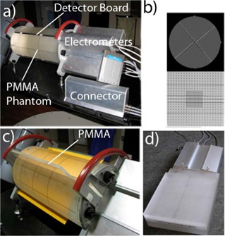
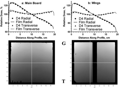
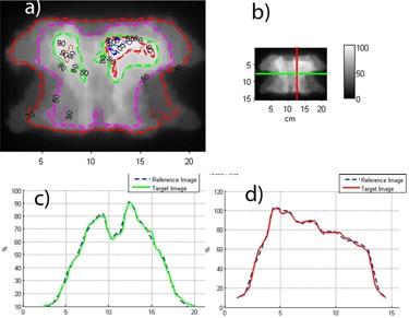
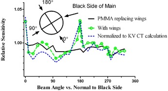
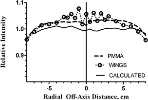
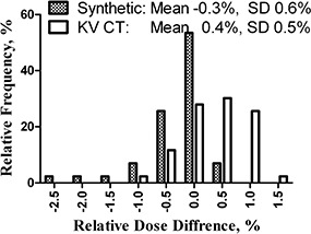
In this paper, we described and characterized a novel biplanar diode array, and demonstrated its applicability to dosimetric QA of the step-and-shoot IMRT. It is the first commercially available device of its kind specifically designed for measurements at varying gantry angles. The detector consists of a cylindrical PMMA phantom with two orthogonal detector boards. There are a total of 1069 p-type 1 mm wide diode detectors covering the measurement area of 20 x 20 cm2 in each of the measurement planes. The orthogonal detector arrays ensure that the dose modulation information is not lost regardless of the beam incidence angle. For absolute calibration, the dose to the reference detector is calculated at the appropriate SSD and radiological depth by the treatment planning system and is scaled by the measured accelerator output. The directly measured rotational response on the central axis shows the maximum variation of approximately +/-3% in the narrow +/-1 degree angular intervals centered on the detector boards. This variation is reduced to less than +/- 2% outside of the four similarly centered +/-5 degrees angular intervals. For all detectors, the difference between the measured and calculated dose for a plan with twelve equally spaced beams is -0.2+/-0.9%. Of eleven IMRT plans, ten passed the gamma(3%,3mm) criterion at or above 95%, while one passed at 92%. Delta4 is a useful tool for IMRT QA, allowing for essentially instantaneous on-line analysis of absolute dose errors in 3D.
Figures
References
-
- Intensity Modulated Radiation Therapy Collaborative Working Group. Intensity‐modulated radiotherapy: current status and issues of interest. Int J Radiat Oncol Biol Phys. 2001;51(4):880–914. - PubMed
-
- Pai S, Das IJ, Dempsey JF, et al. TG‐69: radiographic film for megavoltage beam dosimetry. Med Phys. 2007;34(6):2228–58. - PubMed
-
- Zeidan OA, Stephenson SA, Meeks SL, et al. Characterization and use of EBT radiochromic film for IMRT dose verification. Med Phys. 2006;33(11):4064–72. - PubMed
-
- Wilcox E, Daskalov G, Nedialkova L. Comparison of the epson expression 1680 flatbed and the vidar VXR‐16 dosimetry PRO film scanners for use in IMRT dosimetry using gafchromic and radiographic film. Med Phys. 2007;34(1):41–48. - PubMed
Publication types
MeSH terms
LinkOut - more resources
Full Text Sources
Other Literature Sources
