. 2009 Dec 14;187(6):921-33.
doi: 10.1083/jcb.200908067.

The dynein regulatory complex is the nexin link and a major regulatory node in cilia and flagella

Affiliations

The dynein regulatory complex is the nexin link and a major regulatory node in cilia and flagella

Thomas Heuser et al. J Cell Biol. .

Abstract

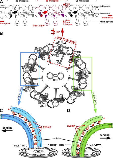
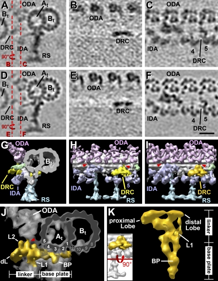
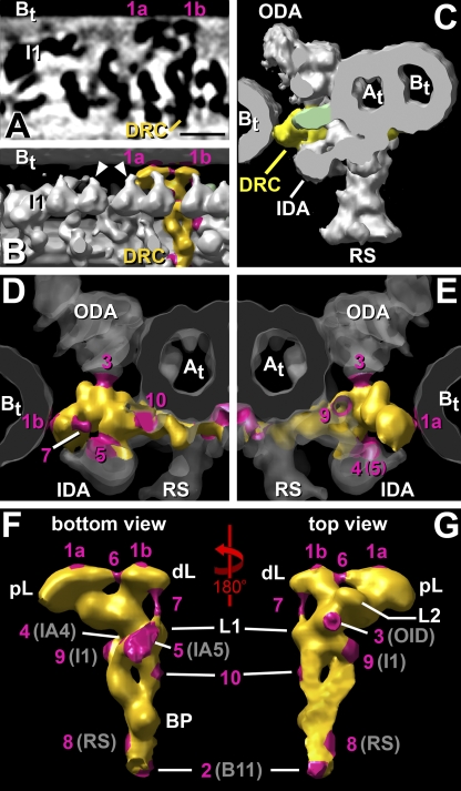
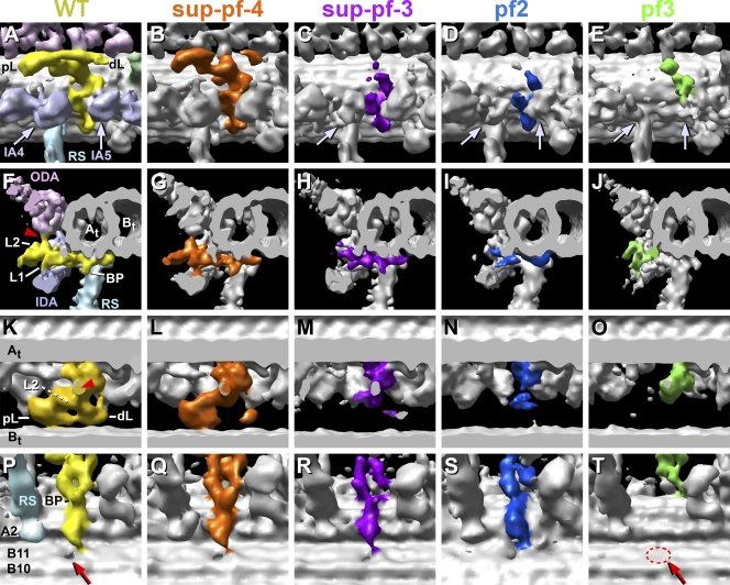
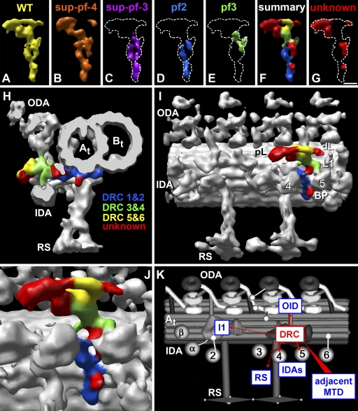
Cilia and flagella are highly conserved microtubule (MT)-based organelles with motile and sensory functions, and ciliary defects have been linked to several human diseases. The 9 + 2 structure of motile axonemes contains nine MT doublets interconnected by nexin links, which surround a central pair of singlet MTs. Motility is generated by the orchestrated activity of thousands of dynein motors, which drive interdoublet sliding. A key regulator of motor activity is the dynein regulatory complex (DRC), but detailed structural information is lacking. Using cryoelectron tomography of wild-type and mutant axonemes from Chlamydomonas reinhardtii, we visualized the DRC in situ at molecular resolution. We present the three-dimensional structure of the DRC, including a model for its subunit organization and intermolecular connections that establish the DRC as a major regulatory node. We further demonstrate that the DRC is the nexin link, which is thought to be critical for the generation of axonemal bending.


Figures

Figure 1.
Figure 1.
Schematic models showing the general organization of cilia and flagella and a model for the conversion of MTD sliding to bending. (A) Longitudinal view of an MTD with three 96-nm repeats shown in front view, i.e., looking from a neighboring B-tubule toward the A-tubule with its attached IDAs and ODAs. This is the classical view of the DRC density seen in previous EM studies (Mastronarde et al., 1992; Gardner et al., 1994). Red arrows indicate the orientation of additional views used in our figures: “view from bottom” looks at the 96-nm repeat from the center of the axoneme outwards, “from top” looks from the ODAs toward the axoneme center, “from prox.” is viewed from the flagellar base to its tip, and “from distal” is vice versa. (B) Simplified cross-sectional view of an axoneme with nine outer MTDs surrounding the CP complex (CPC); the viewing direction is from the flagellar tip (from distal). Three structures connect neighboring MTDs, the ODAs and IDAs and the nexin link (also called the circumferential link). One MTD is boxed in red and shown in longitudinal view in A. The blue and green boxes each highlight a pair of neighboring doublets from opposite sides of the axoneme. (C and D) Restricted interdoublet sliding model for ciliary and flagellar bend formation (Satir, 1968; Summers and Gibbons, 1971). Two pairs of MTDs from opposite sides of the axoneme, as highlighted in B, are shown. The dynein arms are anchored on the cargo MTD in an ATP-independent manner and walk toward the minus end (−) of the track MTD in an ATP-dependent manner, which causes sliding between neighboring MTDs. The links between MTDs are thought to be important for restricting and transforming MT sliding into bending. Note that the minus end–directed dynein motors (red) have to be active and produce MT sliding on alternate sides of the axoneme (switching between the blue and green side) to generate the effective and reverse bend (with opposite bending directions; black arrows). Panel A is adapted from Porter and Sale (2000). Panel B is adapted from Nicastro et al. (2006) with permission from Science.
Figure 2.
Figure 2.
Views of the DRC in WT and a rescued drc mutant with WT phenotype (pWT). (A–F) Tomographic slices through averages of the 96-nm repeat obtained from WT (A–C) and a rescued pf2 mutant, pWT (D–F), showing the DRC in cross (A and D) and longitudinal sections (B, C, E, and F). The dashed red lines in A and D indicate the positions of the slices shown in the longitudinal views (B, C, E, and F); i.e., slices B and E are located close to the neighboring B-tubule (Bt; left), whereas slices C and F were taken closer to the A-tubule (At) of the doublet to which the DRC is attached. (G–K) 3D visualizations using isosurface rendering of averaged 96-nm repeats from WT (G and H) and pWT (I–K) in longitudinal front view (H and I), longitudinal bottom view (K), and cross-sectional view (G and J; for additional explanation of bottom and front views, see Fig. 1). (G–I) Overviews showing the general shape of the DRC in WT (G and H) and pWT (I) and its location within the 96-nm repeat in relation to other axonemal structures, including the two OID linkers (red arrowheads). Note that the IDAs just below the DRC are IA4 and -5. The light green–colored protrusion is an uncharacterized feature, which was previously proposed as a candidate for the nexin link (Bui et al., 2008). (J and K) Simplified surface-rendering visualization of the DRC (gold) represented by the pWT average, which has the highest resolution among our data. All structures except the DRC are either shown in gray transparency (J) or were removed (K). The DRC structures of WT and pWT are very similar (within the resolution limits) and share the same morphology, which consists of two parts, a base plate reaching from the B-tubule structure B11 to the A-tubule protofilament 4 and a linker that reaches from the A-tubule into the gap between neighboring MTDs. Please note that several different systems for numbering the MT protofilaments in the A- and B-tubules have been used (for review see Linck and Stephens, 2007). For consistency and clarity, we have chosen the system recently proposed by Linck and Stephens (2007). The linker ends in two lobes, the larger proximal lobe and the smaller distal lobe (dL). Four major protrusions can be distinguished: the base plate protrusion (BP), the OID linker (red arrowhead), and the two protrusions (L1 and L2) attached to the linker region. The only difference between WT and pWT is a small additional protrusion at the beginning of the base plate in pWT, which was not visible in WT or the other mutants; thus, it is not part of the common model of the DRC and was excluded from J and K. The inset explains the orientation of the DRC shown in K. Descriptions of the B11 structure have been controversial (Nicastro et al., 2006; Sui and Downing, 2006). Although we clearly observe density at this location, the structure appears thinner than a regular protofilament. The A-tubule is labeled as protofilaments 1–5; the B-tubule is labeled as protofilaments 8–10 and filament 11. Bar, 20 nm.
Figure 3.
Figure 3.
Connections within domains of the DRC and between the DRC and other axonemal structures. (A–G) A tomographic slice (A) and surface-rendering visualizations (B–G) of averaged 96-nm repeats of WT (C) and pWT (A, B, and D–G) are shown. A total of 10 connections are shown from different orientations. The connections are colored in magenta (isosurface and numbers 1–10). The DRC is colored yellow in WT (C) and gold in pWT (A, B, and D–G). (A–C) The DRC is the only structure in addition to the dynein arms that forms a continuous connection to the B-tubule (Bt) of the neighboring MTD (connections 1a and 1b), demonstrating that the DRC linker is the nexin link. (A and B) Similar bottom views of the DRC, but shown as tomographic slice (A) and surface-rendering representation (B). The position of the dynein stalks (arrowheads) and the IC–LC complex of the I1 dynein are indicated. (C) The cross-sectional view of WT shows that the DRC connects neighboring MTDs, whereas the uncharacterized protrusion (light green) distal of the DRC does not reach the neighboring B-tubule. (D–G) Surface renderings of the DRC and its connections to various axonemal structures from different viewpoints: distal (D), proximal (E), bottom (F), and top (G). Note that to allow better views of the DRC, different axonemal structures surrounding the DRC have been made transparent (D and E) or removed (F and G). Summary of connections: 1a and 1b, proximal and distal lobe (pL and dL) of the nexin link to neighboring B-tubule; 2, base plate to B11 structure; 3, OID link to ODA; 4, linker to tail of IA4; 5, L1 protrusion to the IA5 dynein head; 6 and 7, internal connections within the DRC linking the proximal and distal lobes (6) and the distal lobe and the L1 protrusion (7); 8, base plate to RS base; 9, DRC linker to an uncharacterized density that connects to the distal end of the IC–LC complex of I1 dynein; 10, DRC linker to an uncharacterized structure distal of the DRC. The light green protrusion shows an uncharacterized structure that was previously proposed as candidate for the nexin link (Bui et al., 2008). At, A-tubule; BP, base plate protrusion; L1 and L2, linker protrusions 1 and 2. Bar, 20 nm.
Figure 4.
Figure 4.
Comparison of the DRC structure between WT and drc mutants. (A–T) The WT DRC is displayed in yellow (A, F, and P; and pWT in K), and the mutant DRCs are shown in different colors and ordered from left to right by increasing size of structural changes: sup-pf-4 (B, G, L, and Q), sup-pf-3 (C, H, M, and R), pf2 (D, I, N, and S), and pf3 (E, J, O, and T). The averaged 96-nm repeats are visualized by isosurface rendering and are shown from four different viewing directions: longitudinal close-up view from the front (slightly rotated toward the bottom view; A–E), cross-sectional overview from distal end (F–J), and longitudinal close-up from the top (K–O) and bottom (P–T). Different parts of the DRC and associated structures are missing in the mutants. In sup-pf-4, the structural changes are small, with only the L2 protrusion (G and L) and most of the distal lobe (dL) missing (B and L). In all of the other mutants, both the proximal and distal lobes (pL and dL) and the L2 protrusion are missing; i.e., these strains have no DRC connection to the B-tubule (Bt) of the neighboring doublet (M–O). In addition, the DRC linker, including the OID linker (F and K, red arrowheads) to the ODAs, is reduced in length to varying degrees (compare H–J with M–O). In pf3, the entire DRC base plate (E, J, and T), including its protrusion (BP; J and T), connections 2 and 8 (see Fig. S2 J), and the hole (red arrow/dashed red circle) through the B11 structure (T), is missing. The base plate protrusion is also lacking in pf2 (I). The defects in the assembly of IDAs also increase from left to right; i.e., IA4 (A–E, left arrows) is reduced in sup-pf-3 (C) and pf2 (D) and missing in pf3 (E), whereas IA5 (right arrows) is reduced in pf2 (D) and missing in pf3 (E). A-tubule (At) includes protofilament A2; B-tubule includes filaments B10 and -11. The light green protrusion in A is an uncharacterized structure previously proposed as a candidate for the nexin link (Bui et al., 2008). L1, linker protrusion 1.
Figure 5.
Figure 5.
DRC subunit localization and model of the DRC interactions. (A–J) Averaged repeats from WT (A, F, and H–J) and drc mutants (B–E) are visualized by isosurface rendering. (A–E) Bottom views of the DRC structure in WT (A), sup-pf-4 (B), sup-pf-3 (C), pf2 (D), and pf3 (E; coloring as in Fig. 4). The dashed white line represents the shape of the WT DRC for better comparison (C–E and G). (F–J) Proposed locations of the DRC subunits, as suggested by our WT mutant comparisons. We correlated previously published data on missing subunits (Huang et al., 1982; Piperno et al. 1994) with structural data on the presence or absence of specific DRC features in the different drc mutants (see Discussion section “Location of DRC subunits within the NDRC”). The suggested locations of DRC subunits are summarized and colored (see color legend in H) within the WT DRC structure (F and H–J), which is shown from the bottom (F), in cross section (H), and as and overview (I) and close-up (J) in a longitudinal front-bottom view. The WT mutant comparison also revealed DRC structures that could not be correlated to the published biochemical DRC components, suggesting that these densities are unknown DRC subunits (colored red in F–J and highlighted in G). Note that subunit DRC7 was not included in the model because of uncertainty about its presence or absence in different mutants. (K) Simplified model that summarizes the structural connections between the WT DRC with other axonemal structures, indicating potential regulatory interactions. The IDA includes IA2–6 and I1 dynein with IC–LC complex and 1-α- and 1-β-dyneins. At, A-tubule; BP, base plate protrusion; Bt, B-tubule; dL, distal lobe; L1, linker protrusion 1; pL, proximal lobe. Bar, 10 nm.

Similar articles

Cited by

References

    1. Böttcher B., Wynne S.A., Crowther R.A. 1997. Determination of the fold of the core protein of hepatitis B virus by electron cryomicroscopy. Nature. 386:88–91 10.1038/386088a0 - DOI - PubMed
    1. Bower R., VanderWaal K., O'Toole E., Fox L., Perrone C., Mueller J., Wirschell M., Kamiya R., Sale W.S., Porter M.E. 2009. IC138 defines a subdomain at the base of the I1 dynein that regulates microtubule sliding and flagellar motility. Mol. Biol. Cell. 20:3055–3063 10.1091/mbc.E09-04-0277 - DOI - PMC - PubMed
    1. Bozkurt H.H., Woolley D.M. 1993. Morphology of nexin links in relation to interdoublet sliding in the sperm flagellum. Cell Motil. Cytoskeleton. 24:109–118 10.1002/cm.970240204 - DOI - PubMed
    1. Brokaw C.J., Kamiya R. 1987. Bending patterns of Chlamydomonas flagella: IV. Mutants with defects in inner and outer dynein arms indicate differences in dynein arm function. Cell Motil. Cytoskeleton. 8:68–75 10.1002/cm.970080110 - DOI - PubMed
    1. Brokaw C.J., Luck D.J.L. 1985. Bending patterns of chlamydomonas flagella: III. A radial spoke head deficient mutant and a central pair deficient mutant. Cell Motil. 5:195–208 10.1002/cm.970050303 - DOI - PubMed

Publication types

MeSH terms