. 2010 Jan 7;55(1):265-80.
doi: 10.1088/0031-9155/55/1/016.

Studies of the interactions of an MRI system with the shielding in a combined PET/MRI scanner

Affiliations

Studies of the interactions of an MRI system with the shielding in a combined PET/MRI scanner

Bo J Peng et al. Phys Med Biol. .

Abstract

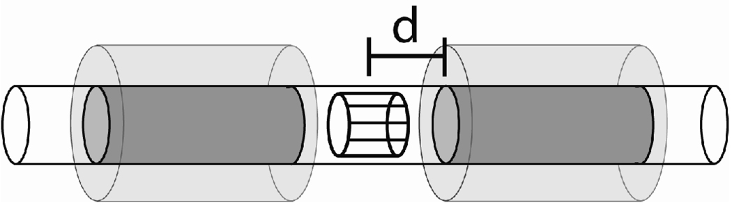
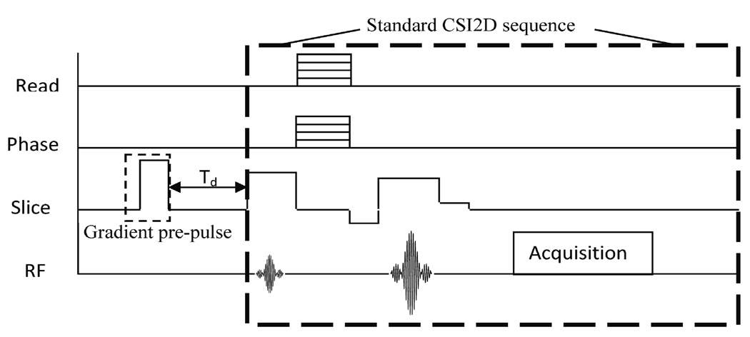
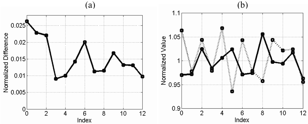
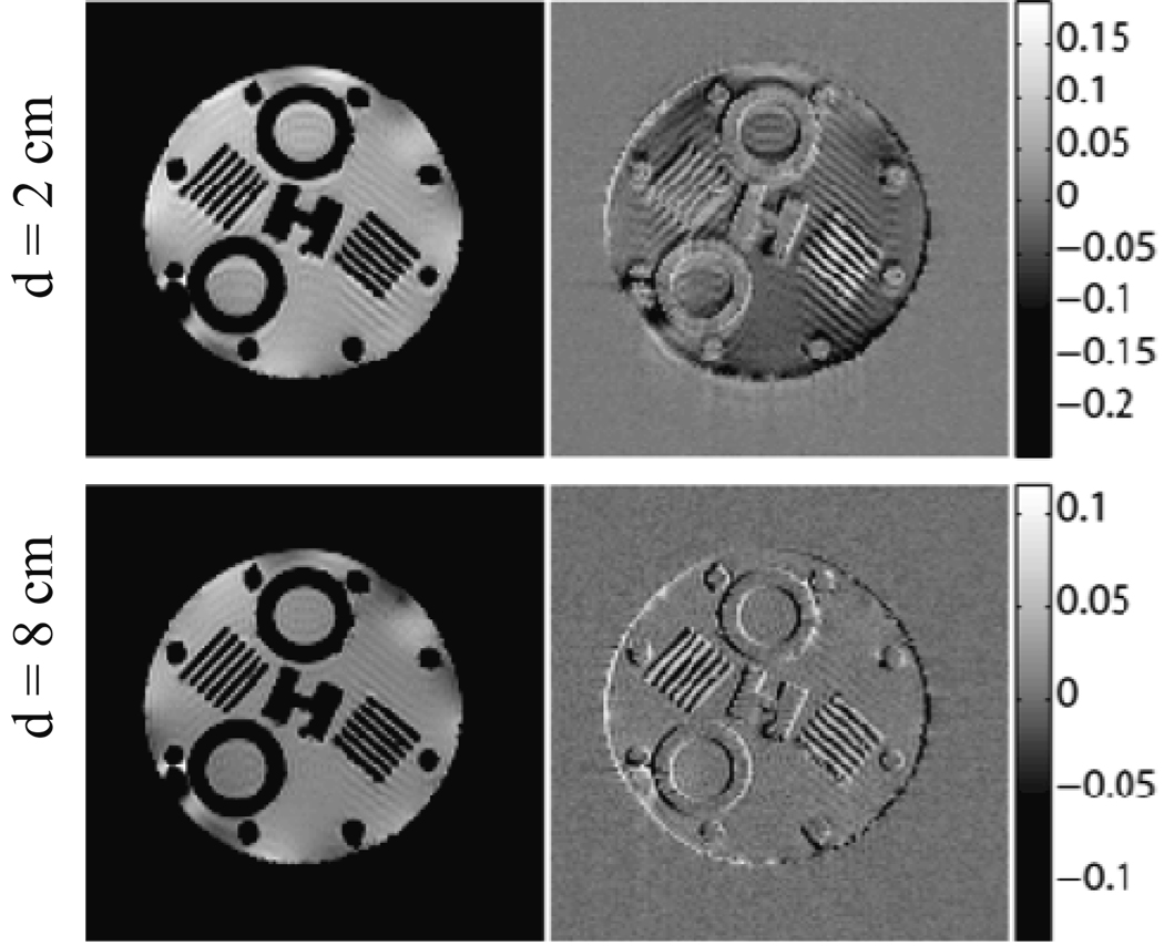
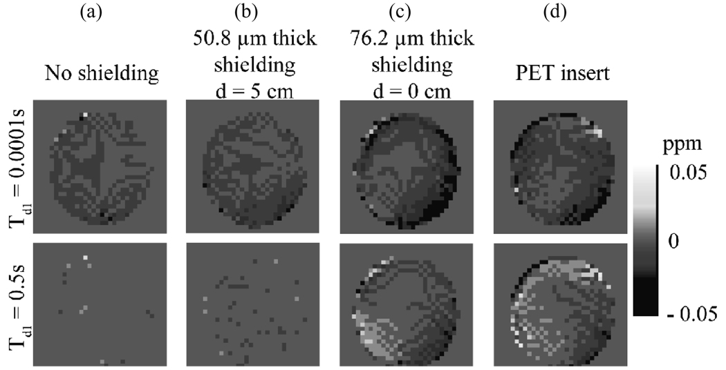
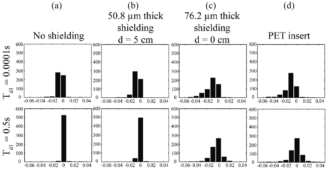
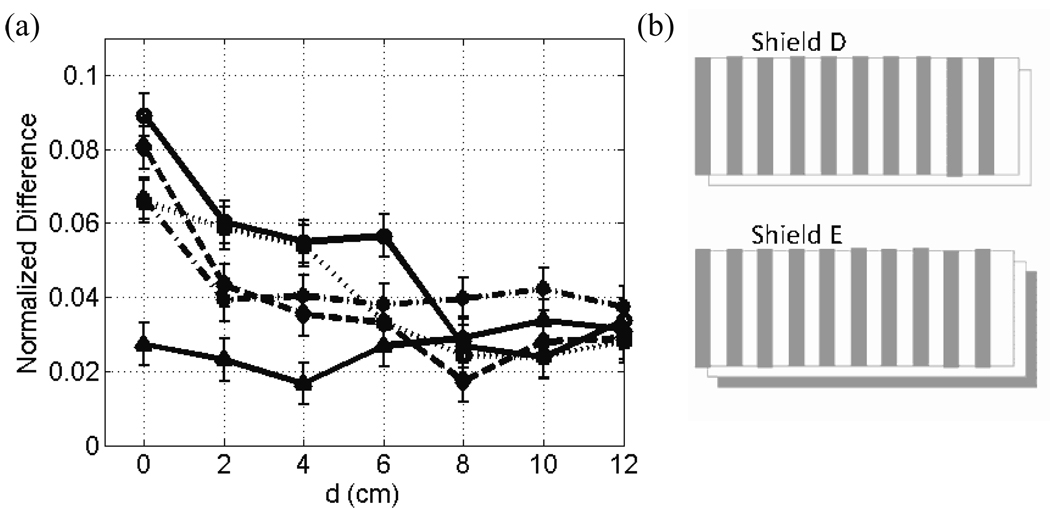
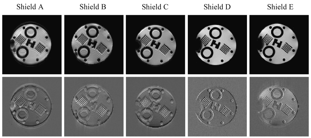
A positron emission tomography (PET) system or 'insert' has been constructed for placement and operation in the bore of a small animal magnetic resonance imaging (MRI) scanner to allow simultaneous MR and PET imaging. The insert contains electronics, components with a variety of magnetic properties and large continuous sheets of metal--all characteristics of an object that should, by conventional wisdom, never be placed in the bore of an MR scanner, especially near the imaging volume. There are a variety of ways the two systems might be expected to interact that could negatively impact the performance of either or both. In this article, the interaction mechanisms, particularly the impact of the PET insert and shielding on MR imaging, are defined and explored. Additionally, some of the difficulties in quantifying errors introduced into the MR images as a result of the presence of the PET components are demonstrated. Several different approaches are used to characterize image artifacts and determine optimal placement of the shielding. Data are also presented that suggest ways the shielding could be modified to reduce errors and enable placement closer to the isocenter of the magnet.


Figures

Figure 1
Figure 1
Diagram of the shielding geometry (not to scale). The long clear cylinder represented the plastic support tube used for shielding placement experiements. The dark shaded cylinders represent the copper shielding used for out symmetric shielding model placed at a variable axial distance 'd' from the magnet isocenter. (The asymmetric shielding experiments used only, i.e., the right shielding cylinder.) The RF coil is shown inside the plastic tube surrounding the imaging volume at the center. The lightly shaded regions indicates the volume in which the PET electronics and outer shielding is located for the full PET insert. Note that this whole structure is placed inside the MR scanner.
Figure 2
Figure 2
A simple pulse sequence diagram illustrates the modified CSI2D experiment with a gradient pre-pulse inserted in the slice select direction. Td, the time from the pre-pulse to the start of the standard CSI2D sequence was varied.
Figure 3
Figure 3
Baseline error measurement: repeated images were taken of a non-uniform water phantom (reshimming each time) without any shield or tubes present and were analyzed for baseline variation. Plots are shown of (a) NMRSE, (b) normalized SNR (solid line), and normalized linewidth (dashed line) versus repetition index.
Figure 4
Figure 4
Shielding placement experiment: NMRSE versus shielding location (d) is plotted for the symmetric (solid line) and asymmetric (dashed line) shielding models. Error bars are added to give an approximate indication of baseline variation.
Figure 5
Figure 5
GE images are displayed for shielding locations d = 2 cm (top) and d = 8 cm (bottom) using the shielding model. Normalized error (or difference) images with respect to the reference images are shown to the right of each GE image with color bars of error values normalized to reference image maxima.
Figure 6
Figure 6
CSI data give visual representations of induced eddy current fields. These images show maps of the pixel-by-pixel shift in resonance frequency (for CH2) resulting from the gradient pre-pulse (shift from frequency with no pre-pulse). Two different pre-pulse delay times are shown (top row 0.0001 s, bottom row 0.5 s) for four different cases: (a) no shielding present, (b) 50.8 µm (0.002”) symmetric shielding model placed 5 cm from iso-center, (c) 76.2 µm (0.003”) symmetric shielding model placed at iso-center, and (d) the actual PET insert. The color bar at the right indicates the magnitude of the frequency shift in ppm.
Figure 7
Figure 7
Histograms are plotted of the frequency shifts shown in Fig. 6. Results are shown for (a) no shielding, (b) 50.8 µm (0.002”) shielding model at d = 5 cm, (c) 76.2 µm (0.003”) shielding model at d = 0 cm, and (d) the full PET insert. Top (bottom) row corresponds to Td = 0.0001 s (0.5 s).
Figure 8
Figure 8
Plots comparing NMRSE for alterations in the shielding model are shown. NMRSE data versus field location are plotted for five different shields. Shield A (solid line with circles), B (dashed line), and C (dotted line) are continuous copper cylinders of a single layer with a thickness of 76.2 µm, 50.8 µm, and 25.4 µm (0.003”, 0.002”, and 0.001”) respectively. Shield D (solid line with triangles) is 50.8 µm (0.002”) thick with axial gaps. Shield E (dash-dotted line) has two 25.4 µm (0.001”) layers such that the outer one has axial gaps and the inner one is solid. Diagrams of shields D and E are shown unwrapped in (b).
Figure 9
Figure 9
GE images (top row) are shown for five different shielding models. All images were acquired with d = 0 cm. Corresponding normalized error (difference) images, with respect to reference images, are shown in the bottom row. Shields A, B, and C are continuous copper cylinders of a single layer with thickness of 76.2 µm, 50.8 µm, and 25.4 µm (0.003”, 0.002”, and 0.001”) respectively. Shield D is 50.8 µm (0.002”) thick with axial gaps. Shield E has two 25.4 µm (0.001”) thick layers—the outer one with axial gaps.

Similar articles

Cited by

References

    1. Alecci M, Jezzard P. Characterization and reduction of gradient-induced eddy currents in the RF shield of a TEM resonator. Magn Reson Med. 2002;48:404–407. - PubMed
    1. Catana C, Procissi D, Wu Y, Judenhofer MS, Qi J, Pichler BJ, Jacobs RE, Cherry SR. Simultaneous in vivo positron emission tomography and magnetic resonance imaging. Proc Natl Acad Sci U S A. 2008;105:3705–3710. - PMC - PubMed
    1. Catana C, Wu Y, Judenhofer MS, Qi J, Pichler BJ, Cherry SR. Simultaneous acquisition of multislice PET and MR images: initial results with a MR-compatible PET scanner. J Nucl Med. 2006;47:1968–1976. - PubMed
    1. Chinzei K, Kikinis R, Jolesz FA. MR Compatibility of Mechatronic Devices: Design Criteria. 1999;2:1020–1031.
    1. Chinzei K, Miller K. Towards MRI guided surgical manipulator. Med Sci Monit. 2001;7:153–163. - PubMed

Publication types

MeSH terms