. 2008 Nov 19;29(22):1775-1792.
doi: 10.1002/marc.200800381.

Putting Electrospun Nanofibers to Work for Biomedical Research

Affiliations

Putting Electrospun Nanofibers to Work for Biomedical Research

Jingwei Xie et al. Macromol Rapid Commun. .

Abstract

Electrospinning has been exploited for almost one century to process polymers and related materials into nanofibers with controllable compositions, diameters, porosities, and porous structures for a variety of applications. Owing to its high porosity and large surface area, a non-woven mat of electrospun nanofibers can serve as an ideal scaffold to mimic the extracellular matrix for cell attachment and nutrient transportation. The nanofiber itself can also be functionalized through encapsulation or attachment of bioactive species such as extracellular matrix proteins, enzymes, and growth factors. In addition, the nanofibers can be further assembled into a variety of arrays or architectures by manipulating their alignment, stacking, or folding. All these attributes make electrospinning a powerful tool for generating nanostructured materials for a range of biomedical applications that include controlled release, drug delivery, and tissue engineering.


Figures

Figure 1
Figure 1
A typical setup for electrospinning, which includes three major components: a high voltage generator, a spinneret (in this case, a flat-end needle), and a collector (in this case, a piece of aluminum foil).
Figure 2
Figure 2
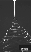
Photographs of typical electrospinning jets captured using a high-speed camera showing the electrically driven bending instability. Reproduced with permission from ref.[8], Copyright 2007 Elsevier.
Figure 3
Figure 3
Electrospun poly(l-lactide) (PLA) fibers having various structures: A) beaded porous fibers; B) highly porous, uniform fibers; C) belt-shaped solid fibers; and D) uniform solid fibers with a circular cross section. In the preparation of samples A and B, the feeding rate for the polymer solution was 0.8 and 0.5 mL · h−1, respectively, and the concentrations of PLA in DCM was 0.8 and 1.3%, respectively. In the preparation of sample C, the feeding rate for the polymer solution was 0.8 mL · h−1 and the concentration of PLA in DCM/DMF (80: 20) was 1.3%. In the preparation of sample D, the feeding rate was 0.5 mL · h−1 and the concentration of PLA in DCM was 0.8%, together with 5×10⁻³ m TCAB.
Figure 4
Figure 4
A) SEM image of PS porous fibers prepared by electrospinning into liquid nitrogen, followed by drying under vacuum. The inset gives an SEM image of the broken end of a fiber at a higher magnification, indicating the fiber was porous throughout. B) TEM of the porous PS fibers shown in (A) with insets at higher magnifications. Reproduced with permission from ref.[89] Copyright 2006 American Chemical Society.
Figure 5
Figure 5
A) Schematic illustrating fabrication of tubular nanofibers by electrospinning with a coaxial spinneret. Reproduced with permission from ref.[91] Copyright 2005 The Royal Society of Chemistry. B) TEM and C) SEM images of TiO2/poly(vinyl pyrrolidone) (PVP) composite tubular nanofibers prepared by electrospinning with a coaxial spinneret, where the inner liquid was mineral oil and the outer liquid was an alcohol solution of PVP and Ti(OiPr)4. Reproduced with permission from ref.[92] Copyright 2004 American Chemical Society.
Figure 6
Figure 6
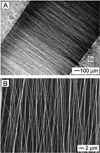
Micrographs showing the alignment of poly(vinyl pyrrolidone) (PVP) nanofibers across a void gap between two pieces of conductive silicon substrates: A) dark-field optical micrograph; and B) SEM image from the same sample. Reproduced with the permission from ref.[101] Copyright 2003 American Chemical Society.
Figure 7
Figure 7
A) Schematic illustrations of patterns composed of two pairs of electrodes. B) Optical micrograph of poly(vinyl pyrrolidone) (PVP) nanofibers collected in the center area of the electrodes shown in (A). During collection, the electrode pairs of 1,3 and 2,4 were alternatively grounded for ≈5 s. C) Schematic illustrations of patterns composed of three pairs of electrodes. D) Optical micrograph of a tri-layer mesh of PVP nanofibers which were collected in the center area of the electrodes shown in (C). The electrode pairs of 1,4, 2,5, and 3,6 were sequentially grounded for ≈ 5 s to collect alternating layers with orientations of their fibers rotated by around 60°. Reproduced with permission from ref.[106] Copyright 2004 Wiley InterScience.
Figure 8
Figure 8
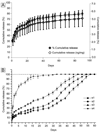
In vitro release profiles: A) Glia cell-derived neurotrophic factor from electrospun poly[(ε-caprolactone)-co-(ethyl ethylene phosphate)] fibers; B) Bone morphogenic protein 2 (BMP-2) release from poly(lactide-co-glycolide)/hydroxyapatite fibrous scaffold. s1–s3: the BMP-2 solution was added directly into the aqueous fabrication solution for electrospinning which contains different amounts of hydroxylapatite nanoparticles; s4: the BMP-2 protein was added to each fibrous scaffold sample of s4 after scaffold was fabricated and dried for 3 d using a freeze drier. Reproduced with permission from ref.[121,122] Copyright 2007 and 2008 Wiley InterScience.
Figure 9
Figure 9
Illustration of encapsulation of DNA inside electrospun fibers. Reproduced with permission from ref.[127] Copyright 2006 Institute of Physics and IOP publishing.
Figure 10
Figure 10
Neurite outgrowth from dorsal root ganglia tissue on nanofibers. Immunofluorescent staining of neurofilaments was used to visualize neurite outgrowth from dorsal root ganglia tissue on (A) untreated random poly(l-lactide) (PLLA) nanofibers, (B) untreated aligned PLLA nanofibers, and (C) immobilized-basic fibroblast growth factor on aligned PLLA nanofibers after 6 d of ex vivo culture. Reproduced with permission from ref.[138] Copyright 2007 the American Chemical Society.
Figure 11
Figure 11
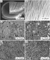
A) Cross-sectional view of nerve conduits with aligned electrospun fibers; B) aligned poly[(ε-caprolactone)-co-(ethyl ethylene phosphate)] (PCL-EEP) fibers in nerve conduits; (C–F) optical micrographs of the cross sections of regenerated sciatic nerves and tubes were composed of: C) PCL-EEP film; D) plain PCL-EEP electrospun fibers aligned longitudinally; E) plain PCL-EEP electrospun fibers aligned circumferentially; F) glia-derived nerve factors loaded-PCL-EEP fibers aligned longitudinally. Dashed circles indicate voids left over by PCL-EEP electrospun fibers. Reproduced with the permission from ref.[121] Copyright 2007 Wiley InterScience.
Figure 12
Figure 12
Nude mice tibia bone regeneration experiments with the electrospun poly(lactide-co-glycolide)/hydroxyapatite (PLGA/HA) composite fibers as scaffolds: (top panel) control (without any implantation); and (bottom panel) the PLGA/HA fibrous scaffolds which were added in bone morphogenic protein 2 solution after electrospinning for adsorption. White arrows indicate the delayed-union of bone fractures. Reproduced with permission from ref.[122] Copyright 2008 Wiley InterScience.

Similar articles

Cited by

References

    1. Li D, Xia Y. Adv. Mater. 2004;16:1151.
    1. U.S. 1 975 504 (1934), invs.: A. Formhals.

    1. Dzenis Y. Science. 2004;304:1917. - PubMed
    1. Li D, McCann JT, Xia Y. J. Am. Ceram. Soc. 2006;89:1861.
    1. Rutledge GC, Fridrikh SV. Adv. Drug Delivery Rev. 2007;59:1384. - PubMed

LinkOut - more resources