

Comparing polyelectrolyte multilayer-coated PMMA microfluidic devices and glass microchips for electrophoretic separations
- PMID: 20013912
- PMCID: PMC2847454
- DOI: 10.1002/elps.200900403
Comparing polyelectrolyte multilayer-coated PMMA microfluidic devices and glass microchips for electrophoretic separations
Abstract
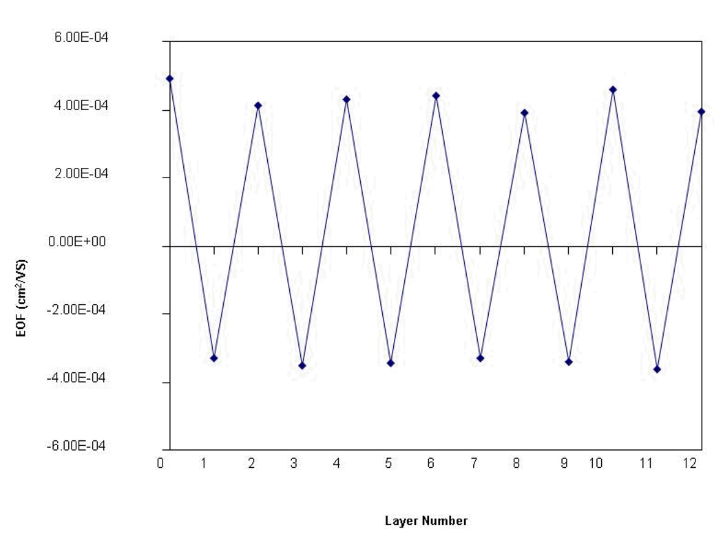
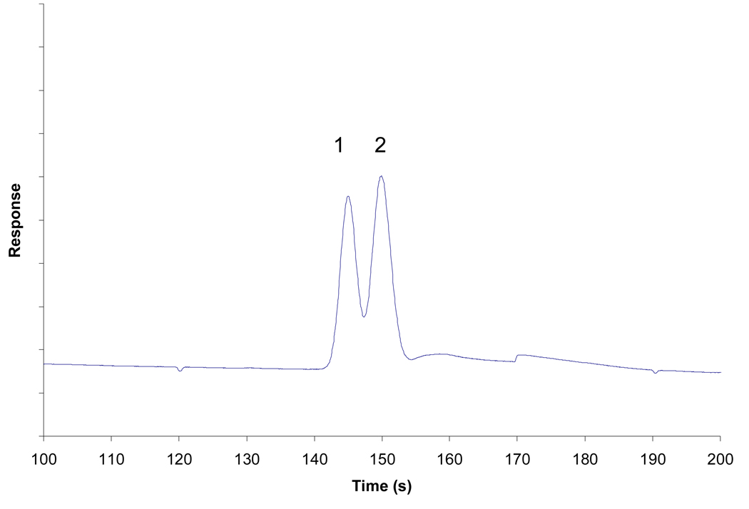
There is a continuing drive in microfluidics to transfer microchip systems from the more expensive glass microchips to cheaper polymer microchips. Here, we investigate using polyelectrolyte multilayers (PEM) as a coating system for PMMA microchips to improve their functionality. The multilayer system was prepared by layer-to-layer deposition of poly(diallyldimethylammonium) chloride and polystyrene sulfonate. Practical aspects of coating PMMA microchips were explored. The multilayer buildup process was monitored using EOF measurements, and the stability of the PEM was investigated. The performance of the PEM-PMMA microchip was compared with those of a standard glass microchip and a PEM-glass microchip in terms of EOF and separating two fluorescent dyes. Several key findings in the development of the multilayer coating procedure for PMMA chips are also presented. It was found that, with careful preparation, a PEM-PMMA microchip can be prepared that has properties comparable--and in some cases superior--to those of a standard glass microchip.
Figures
Similar articles
-
Fabrication of PMMA microfluidic chips using disposable agar hydrogel templates.Electrophoresis. 2009 Dec;30(24):4225-9. doi: 10.1002/elps.200900502. Electrophoresis. 2009. PMID: 20013907
-
Plasticizer-assisted bonding of poly(methyl methacrylate) microfluidic chips at low temperature.J Chromatogr A. 2010 Jan 1;1217(1):160-6. doi: 10.1016/j.chroma.2009.11.018. Epub 2009 Nov 10. J Chromatogr A. 2010. PMID: 19945714
-
Rapid prototyping of poly(methyl methacrylate) microfluidic systems using solvent imprinting and bonding.J Chromatogr A. 2007 Aug 31;1162(2):162-6. doi: 10.1016/j.chroma.2007.04.002. Epub 2007 Apr 8. J Chromatogr A. 2007. PMID: 17466320 Free PMC article.
-
Wall coating for capillary electrophoresis on microchips.Electrophoresis. 2004 Nov;25(21-22):3589-601. doi: 10.1002/elps.200406113. Electrophoresis. 2004. PMID: 15565710 Review.
-
CE microchips: an opened gate to food analysis.Electrophoresis. 2007 Mar;28(6):1002-11. doi: 10.1002/elps.200600412. Electrophoresis. 2007. PMID: 17370302 Review.
Cited by
-
Cationic isotachophoresis separation of the biomarker cardiac troponin I from a high-abundance contaminant, serum albumin.Electrophoresis. 2014 Jul;35(14):2029-38. doi: 10.1002/elps.201400009. Epub 2014 Jun 5. Electrophoresis. 2014. PMID: 24723384 Free PMC article.
References
-
- Harrison DJ, Seiler K, Manz A, Fan Z. Anal Chem. 1992;64:1926–1932.
-
- Breadmore MC, Shrinivasan S, Karlinsey J, Ferrance JP, Norris PM, Landers JP. Electrophoresis. 2003;24:1261–1270. - PubMed
-
- Becker H, Gartner C. Anal Bioanal Chem. 2008;390:89–111. - PubMed
-
- Piruska A, Nikcevi I, Lee SH, Ahn C, Heineman WR, Limbach PA, Seliskar CJ. Lab on a Chip. 2005;5:1348–1354. - PubMed
-
- Wu Z, Xanthopoulos N, Reymond F, Rossier J, Girault HH. Electrophoresis. 2002;23:782–790. - PubMed
Publication types
MeSH terms
Substances
Grants and funding
LinkOut - more resources
Full Text Sources
Research Materials
