

Micro-macro hybrid soft-lithography master (MMHSM) fabrication for lab-on-a-chip applications
- PMID: 20049640
- PMCID: PMC2864814
- DOI: 10.1007/s10544-009-9390-9
Micro-macro hybrid soft-lithography master (MMHSM) fabrication for lab-on-a-chip applications
Abstract
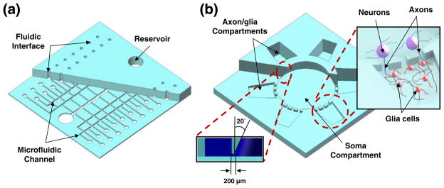
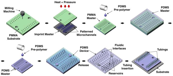
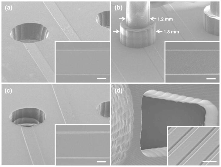
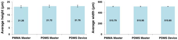
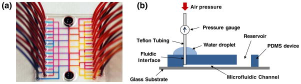
We present a novel micro-macro hybrid soft-lithography master (MMHSM) fabrication technique where microdevices having both microscale and macroscale features can be replicated with a single soft-lithography step. A poly(methyl methacrylate) (PMMA) master having macroscale structures was first created by a bench-top milling machine. An imprinting master mold having microscale structures was then imprinted on the PMMA surface through a hot-embossing process to obtain a PMMA master mold. A poly(dimethylsiloxane) (PDMS) master was then replicated from this PMMA master through a standard soft-lithography process. This process allowed both microscale (height: 3-20 microm, width: 20-500 microm) and macroscale (height: 3.5 mm, width: 1.2-7 mm) structures to co-exist on the PDMS master mold, from which final PDMS devices could be easily stamped out in large quantities. Microfluidic structures requiring macroscale dimensions in height, such as reservoirs or fluidic tubing interconnects, could be directly built into PDMS microfluidic devices without the typically used manual punching process. This significantly reduced alignment errors and time required for such manual fabrication steps. In this paper, we successfully demonstrated the utility of this novel hybrid fabrication method by fabricating a PDMS microfluidic device with 40 built-in fluidic interfaces and a PDMS multi-compartment neuron co-culture platform, where millimeter-scale compartments are connected via arrays of 20 microm wide and 200 microm long microfluidic channels. The resulting structures were characterized for the integrity of the transferred pattern sizes and the surface roughness using scanning electron microscopy and optical profilometry.
Keywords: Cast molding; Fluidic interface; PDMS; Soft-lithography.
Figures
Similar articles
-
A multi-compartment CNS neuron-glia Co-culture microfluidic platform.J Vis Exp. 2009 Sep 10;(31):1399. doi: 10.3791/1399. J Vis Exp. 2009. PMID: 19745806 Free PMC article.
-
Fabrication of a cyclic olefin copolymer planar waveguide embedded in a multi-channel poly(methyl methacrylate) fluidic chip for evanescence excitation.Lab Chip. 2010 Jan 7;10(1):66-73. doi: 10.1039/b908759a. Epub 2009 Nov 4. Lab Chip. 2010. PMID: 20024052 Free PMC article.
-
Fabrication of thermoset polyester microfluidic devices and embossing masters using rapid prototyped polydimethylsiloxane molds.Lab Chip. 2003 Aug;3(3):158-63. doi: 10.1039/b305074m. Epub 2003 Jul 7. Lab Chip. 2003. PMID: 15100767
-
The upcoming 3D-printing revolution in microfluidics.Lab Chip. 2016 May 21;16(10):1720-42. doi: 10.1039/c6lc00163g. Epub 2016 Apr 21. Lab Chip. 2016. PMID: 27101171 Free PMC article. Review.
-
Rapid Manufacturing of Multilayered Microfluidic Devices for Organ on a Chip Applications.Sensors (Basel). 2021 Feb 16;21(4):1382. doi: 10.3390/s21041382. Sensors (Basel). 2021. PMID: 33669434 Free PMC article. Review.
Cited by
-
Multi-compartment neuron-glia co-culture platform for localized CNS axon-glia interaction study.Lab Chip. 2012 Sep 21;12(18):3296-304. doi: 10.1039/c2lc40303j. Epub 2012 Jul 24. Lab Chip. 2012. PMID: 22828584 Free PMC article.
-
Micro-Macro: Selective Integration of Microfeatures Inside Low-Cost Macromolds for PDMS Microfluidics Fabrication.Micromachines (Basel). 2019 Aug 30;10(9):576. doi: 10.3390/mi10090576. Micromachines (Basel). 2019. PMID: 31480301 Free PMC article.
-
Organic Anion Transporting Polypeptide 2B1 in Human Fetal Membranes: A Novel Gatekeeper for Drug Transport During Pregnancy?Front Pharmacol. 2021 Dec 20;12:771818. doi: 10.3389/fphar.2021.771818. eCollection 2021. Front Pharmacol. 2021. PMID: 34987396 Free PMC article.
-
Molecular mechanisms of environmental toxin cadmium at the feto-maternal interface investigated using an organ-on-chip (FMi-OOC) model.J Hazard Mater. 2022 Jan 15;422:126759. doi: 10.1016/j.jhazmat.2021.126759. Epub 2021 Aug 2. J Hazard Mater. 2022. PMID: 34391970 Free PMC article.
-
Planar bioadhesive microdevices: a new technology for oral drug delivery.Curr Pharm Biotechnol. 2014;15(7):673-83. doi: 10.2174/1389201015666140915152706. Curr Pharm Biotechnol. 2014. PMID: 25219863 Free PMC article. Review.
References
-
- Bhagat AAS, Jothimuthu P, Pais A, Papautsky I. J Micromech Microeng. 2007;17:42.
-
- Brivio M, Verboom W, Reinhoudt DN. Lab Chip. 2006;6:329. - PubMed
-
- Cho Y, Kim HS, Frazier AB, Chen Z, Shin DM, Han A. J Microelectromech Syst. 2009;18:808.
-
- Choi JW, Oh KW, Han A, Okulan N, Wijayawardhana CA, Lannes C, Bhansali S, Schlueter KT, Heineman WR, Halsall HB, Nevin JH, Helmicki AJ, Henderson HT, Ahn CH. Biomed Microdevices. 2001;3:191.
Publication types
MeSH terms
Substances
Grants and funding
LinkOut - more resources
Full Text Sources
Miscellaneous
