Forward-masking patterns produced by symmetric and asymmetric pulse shapes in electric hearing
- PMID: 20058980
- PMCID: PMC3000474
- DOI: 10.1121/1.3257231
Forward-masking patterns produced by symmetric and asymmetric pulse shapes in electric hearing
Abstract
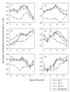
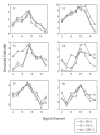
Two forward-masking experiments were conducted with six cochlear implant listeners to test whether asymmetric pulse shapes would improve the place-specificity of stimulation compared to symmetric ones. The maskers were either cathodic-first symmetric biphasic, pseudomonophasic (i.e., with a second anodic phase longer and lower in amplitude than the first phase), or "delayed pseudomonophasic" (identical to pseudomonophasic but with an inter-phase gap) stimuli. In experiment 1, forward-masking patterns for monopolar maskers were obtained by keeping each masker fixed on a middle electrode of the array and measuring the masked thresholds of a monopolar signal presented on several other electrodes. The results were very variable, and no difference between pulse shapes was found. In experiment 2, six maskers were used in a wide bipolar (bipolar+9) configuration: the same three pulse shapes as in experiment 1, either cathodic-first relative to the most apical or relative to the most basal electrode of the bipolar channel. The pseudomonophasic masker showed a stronger excitation proximal to the electrode of the bipolar pair for which the short, high-amplitude phase was anodic. However, no difference was obtained with the symmetric and, more surprisingly, with the delayed pseudomonophasic maskers. Implications for cochlear implant design are discussed.
Figures


Similar articles
-
Spread of excitation varies for different electrical pulse shapes and stimulation modes in cochlear implants.Hear Res. 2012 Aug;290(1-2):21-36. doi: 10.1016/j.heares.2012.05.003. Epub 2012 May 11. Hear Res. 2012. PMID: 22583921
-
Spatial Selectivity in Cochlear Implants: Effects of Asymmetric Waveforms and Development of a Single-Point Measure.J Assoc Res Otolaryngol. 2017 Oct;18(5):711-727. doi: 10.1007/s10162-017-0625-9. Epub 2017 Jul 28. J Assoc Res Otolaryngol. 2017. PMID: 28755309 Free PMC article.
-
Pure-Tone Masking Patterns for Monopolar and Phantom Electrical Stimulation in Cochlear Implants.Ear Hear. 2018 Jan/Feb;39(1):124-130. doi: 10.1097/AUD.0000000000000471. Ear Hear. 2018. PMID: 28700446
-
Across- and within-channel envelope interactions in cochlear implant listeners.J Assoc Res Otolaryngol. 2004 Dec;5(4):360-75. doi: 10.1007/s10162-004-4050-5. J Assoc Res Otolaryngol. 2004. PMID: 15675001 Free PMC article.
-
Forward masking as a method of measuring place specificity of neural excitation in cochlear implants: a review of methods and interpretation.J Acoust Soc Am. 2012 Mar;131(3):2209-24. doi: 10.1121/1.3683248. J Acoust Soc Am. 2012. PMID: 22423717 Review.
Cited by
-
Cochlear Implant Research and Development in the Twenty-first Century: A Critical Update.J Assoc Res Otolaryngol. 2021 Oct;22(5):481-508. doi: 10.1007/s10162-021-00811-5. Epub 2021 Aug 25. J Assoc Res Otolaryngol. 2021. PMID: 34432222 Free PMC article. Review.
-
Effect of Stimulus Polarity on Physiological Spread of Excitation in Cochlear Implants.J Am Acad Audiol. 2017 Oct;28(9):786-798. doi: 10.3766/jaaa.16144. J Am Acad Audiol. 2017. PMID: 28972468 Free PMC article.
-
Effect of Pulse Rate and Polarity on the Sensitivity of Auditory Brainstem and Cochlear Implant Users to Electrical Stimulation.J Assoc Res Otolaryngol. 2015 Oct;16(5):653-68. doi: 10.1007/s10162-015-0530-z. Epub 2015 Jul 3. J Assoc Res Otolaryngol. 2015. PMID: 26138501 Free PMC article.
-
The Effect of Stimulus Polarity on the Relation Between Pitch Ranking and ECAP Spread of Excitation in Cochlear Implant Users.J Assoc Res Otolaryngol. 2019 Jun;20(3):279-290. doi: 10.1007/s10162-018-00712-0. Epub 2019 Jan 31. J Assoc Res Otolaryngol. 2019. PMID: 30706216 Free PMC article.
-
Effects of stimulus level and rate on psychophysical thresholds for interleaved pulse trains in cochlear implants.J Acoust Soc Am. 2016 Oct;140(4):2297. doi: 10.1121/1.4963903. J Acoust Soc Am. 2016. PMID: 27794318 Free PMC article.
References
-
- Abbas PJ, Hughes ML, Brown CJ, Miller CA, South H. Channel interaction in cochlear implant users evaluated using the electrically evoked compound action potential. Audiol.Neurootol. 2004;9:203–213. - PubMed
-
- Badi AN, Hillman T, Shelton C, Normann RA. A technique for implantation of a 3-dimensional penetrating electrode array in the modiolar nerve of cats and humans. Arch.Otolaryngol.Head Neck Surg. 2002;128:1019–1025. - PubMed
-
- Bierer JA. Threshold and channel interaction in cochlear implant users: evaluation of the tripolar electrode configuration. J.Acoust.Soc.Am. 2007;121:1642–1653. - PubMed
-
- Bonham BH, Middlebrooks JC, Rebscher SJ, Snyder RL. The neurophysiological effects of simulated auditory prosthesis stimulation. Third quarterly progress report. 2003. NIH contract N01-DC-02-1006.
-
- Carlyon RP, van Wieringen A, Deeks JM, Long CJ, Lyzenga J, Wouters J. Effect of inter-phase gap on the sensitivity of cochlear implant users to electrical stimulation. Hear.Res. 2005;205:210–224. - PubMed
Publication types
MeSH terms
Grants and funding
LinkOut - more resources
Full Text Sources
Other Literature Sources
Medical
Miscellaneous

