

In vitro and in vivo magnetic resonance imaging (MRI) detection of GFP through magnetization transfer contrast (MTC)
- PMID: 20060482
- PMCID: PMC2824127
- DOI: 10.1016/j.neuroimage.2009.12.111
In vitro and in vivo magnetic resonance imaging (MRI) detection of GFP through magnetization transfer contrast (MTC)
Abstract
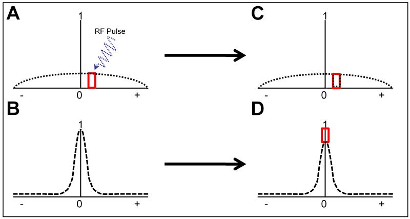
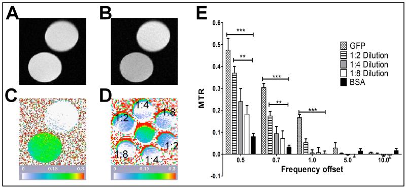
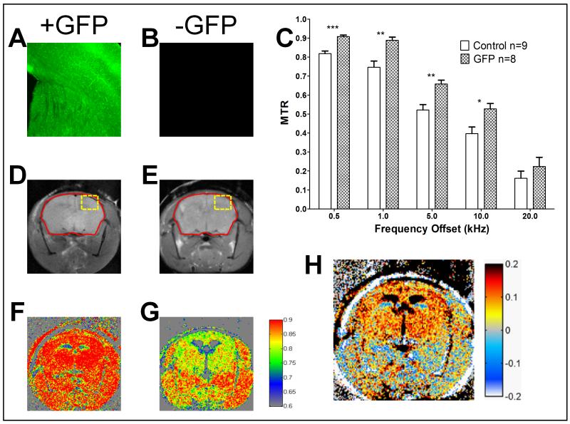
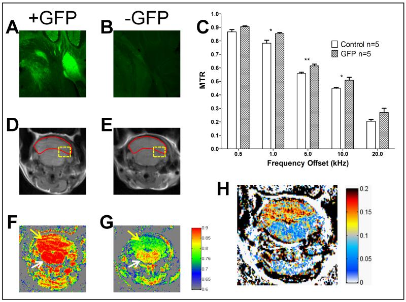
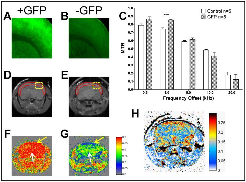
Green fluorescent protein (GFP) is a widely utilized molecular marker of gene expression. However, its use in in vivo imaging has been restricted to transparent tissue mainly due to the tissue penetrance limitation of optical imaging. Here, we report a novel approach to detect GFP with Magnetization transfer contrast (MTC) magnetic resonance imaging (MRI). MTC is an MRI methodology currently utilized to detect macromolecule changes such as decrease in myelin and increase in collagen content. We employed MTC MRI imaging to detect GFP both in vitro and in in vivo mouse models. We demonstrated that our approach produces values that are protein specific, and concentration dependent. This approach provides a flexible, non-invasive in vivo molecular MRI imaging strategy that is dependent upon the presence and concentration of the GFP reporter.
Keywords: Green Fluorescent Protein (GFP); Magnetic Resonance Imaging (MRI); Magnetization Transfer; gene reporter.
Copyright 2009 Elsevier Inc. All rights reserved.
Figures
Similar articles
-
Magnetization transfer contrast MRI in GFP‑tagged live bacteria.Mol Med Rep. 2019 Jan;19(1):617-621. doi: 10.3892/mmr.2018.9669. Epub 2018 Nov 19. Mol Med Rep. 2019. PMID: 30483743 Free PMC article.
-
Magnetization transfer contrast in magnetic resonance imaging.Magn Reson Q. 1992 Jun;8(2):116-37. Magn Reson Q. 1992. PMID: 1622774 Review.
-
Magnetization transfer contrast imaging reveals amyloid pathology in Alzheimer's disease transgenic mice.Neuroimage. 2014 Feb 15;87:111-9. doi: 10.1016/j.neuroimage.2013.10.056. Epub 2013 Nov 2. Neuroimage. 2014. PMID: 24188815
-
Superparamagnetic iron oxide nanoparticle-labeled cells as an effective vehicle for tracking the GFP gene marker using magnetic resonance imaging.Cytotherapy. 2009;11(1):43-51. doi: 10.1080/14653240802420243. Cytotherapy. 2009. PMID: 18956269 Free PMC article.
-
[Magnetization transfer contrast imaging (MTC): its fundamentals, technics and applications].Rofo. 1998 Jul;169(1):3-10. doi: 10.1055/s-2007-1015041. Rofo. 1998. PMID: 9711275 Review. German.
Cited by
-
MRI biosensors: a short primer.J Magn Reson Imaging. 2013 Sep;38(3):530-9. doi: 10.1002/jmri.24298. J Magn Reson Imaging. 2013. PMID: 23996662 Free PMC article. Review.
-
Tissue-Specific Ferritin- and GFP-Based Genetic Vectors Visualize Neurons by MRI in the Intact and Post-Ischemic Rat Brain.Int J Mol Sci. 2020 Nov 25;21(23):8951. doi: 10.3390/ijms21238951. Int J Mol Sci. 2020. PMID: 33255702 Free PMC article.
-
Supercharged green fluorescent proteins as bimodal reporter genes for CEST MRI and optical imaging.Chem Commun (Camb). 2015 Mar 21;51(23):4869-71. doi: 10.1039/c4cc10195b. Chem Commun (Camb). 2015. PMID: 25697683 Free PMC article.
-
Bioengineered probes for molecular magnetic resonance imaging in the nervous system.ACS Chem Neurosci. 2012 Aug 15;3(8):593-602. doi: 10.1021/cn300059r. Epub 2012 Jul 11. ACS Chem Neurosci. 2012. PMID: 22896803 Free PMC article. Review.
-
Magnetization transfer contrast MRI in GFP‑tagged live bacteria.Mol Med Rep. 2019 Jan;19(1):617-621. doi: 10.3892/mmr.2018.9669. Epub 2018 Nov 19. Mol Med Rep. 2019. PMID: 30483743 Free PMC article.
References
-
- Becker A, Hessenius C, Licha K, Ebert B, Sukowski U, Semmler W, Wiedenmann B, Grötzinger C. Receptor-targeted optical imaging of tumors with near-infrared fluorescent ligands. Nat Biotechnol. 2001;19:327–31. - PubMed
-
- Cohen B, Ziv K, Plaks V, Israely T, Kalchenko V, Harmelin A, Benjamin LE, Neeman M. MRI detection of transcriptional regulation of gene expression in transgenic mice. Nat Med. 2007;13:498–503. - PubMed
-
- Edison ES, Bajel A, Chandy M. Iron homeostasis: new players, newer insights. European Journal of Haematology. 2008;81:411–424. - PubMed
-
- Enochs WS, Petherick P, Bogdanova A, Mohr U, Weissleder R. Paramagnetic metal scavenging by melanin: MR imaging. Radiology. 1997;204:417–23. - PubMed
-
- Gilad AA, McMahon MT, Walczak P, Winnard PT, Raman V, van Laarhoven HWM, Skoglund CM, Bulte JWM, van Zijl PCM. Artificial reporter gene providing MRI contrast based on proton exchange. Nat Biotechnol. 2007;25:217–9. - PubMed
Publication types
MeSH terms
Substances
Grants and funding
LinkOut - more resources
Full Text Sources
Other Literature Sources
Medical
