

Preliminary evaluation of a combined microPET-MR system
- PMID: 20082530
- PMCID: PMC4304007
- DOI: 10.1177/153303461000900106
Preliminary evaluation of a combined microPET-MR system
Abstract
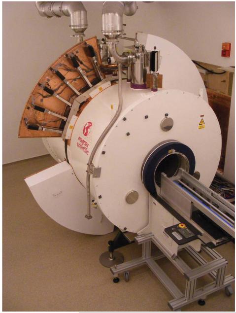
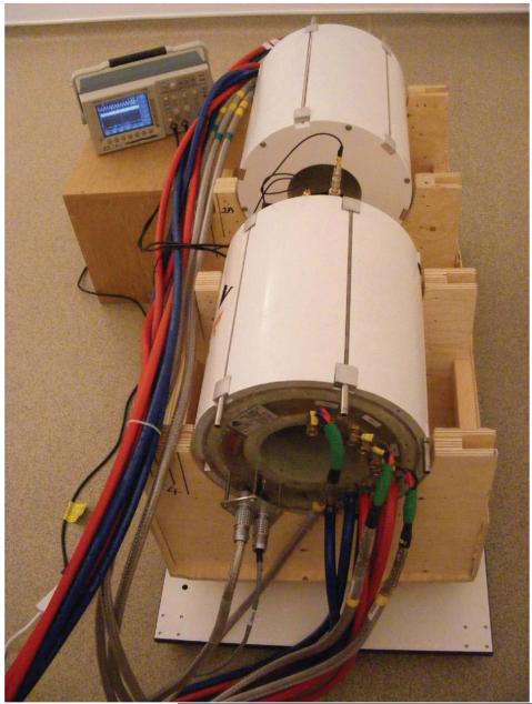
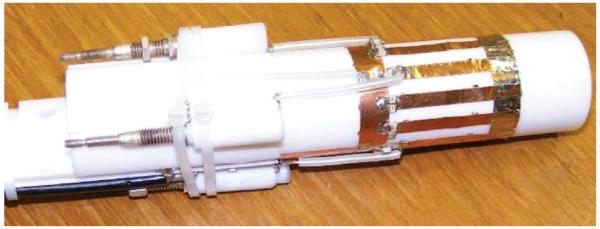
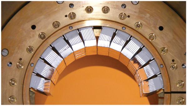
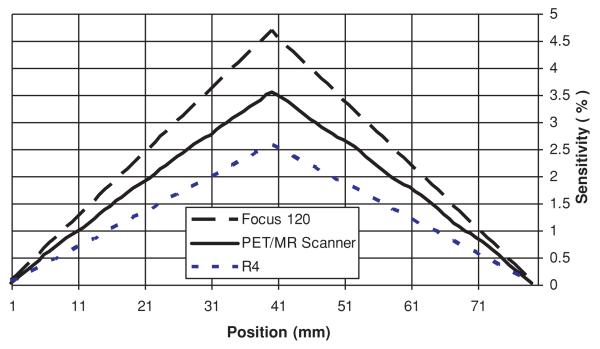
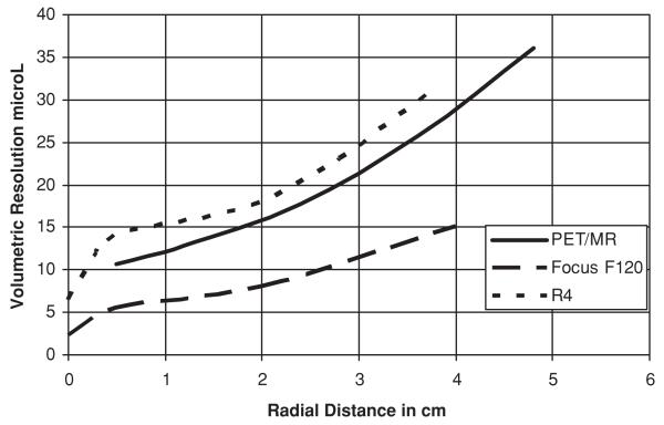
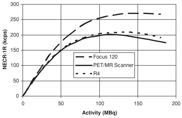
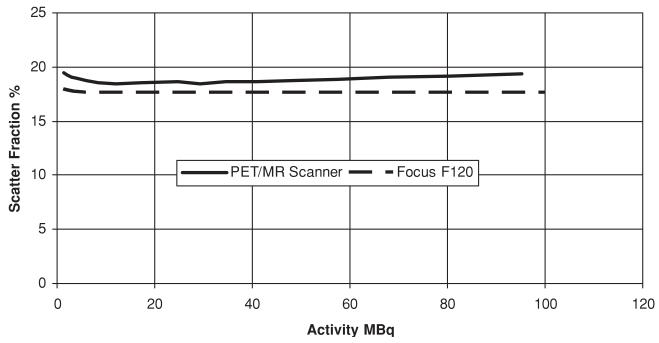
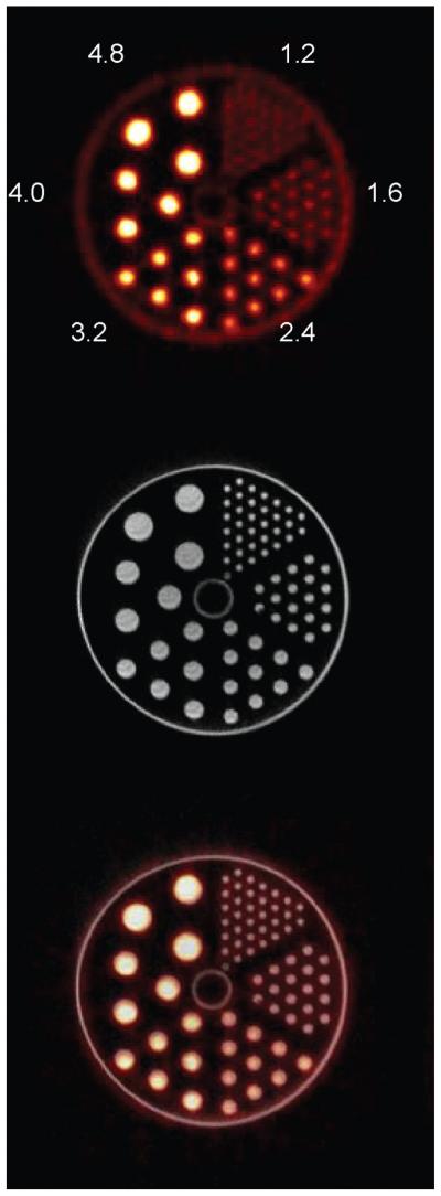
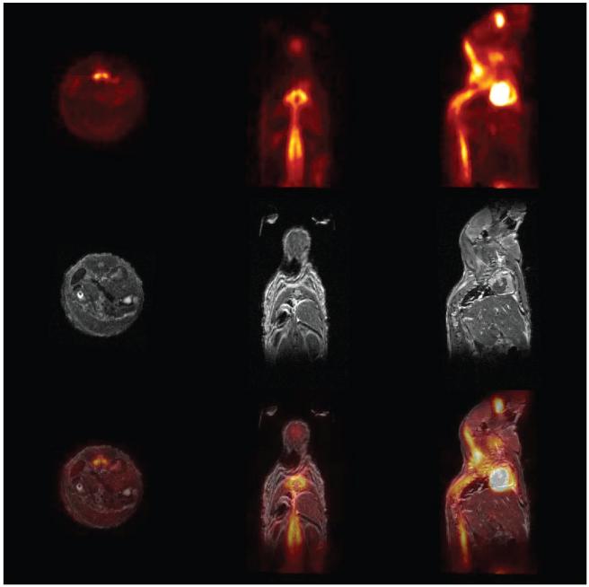
There are many motivations for adding simultaneously acquired MR images to PET scanning. The most straight forward are, superior registration of MR and PET images, the addition of morphological detail when there is non-rigid motion and for pre-clinical studies simultaneous imaging could lead to a significant reduction in the time that animals are required to be anesthetised. In addition simultaneous MR has the potential to provide accurate motion correction for PET image reconstruction. For functional imaging simultaneous acquisition is required to assess the subject in the same physiological state, such as acute stroke studies. The elimination of the additional radiation associated with combining CT with PET, by providing anatomic detail with MR, would be a crucial advantage for cancer screening. Combining the two instruments necessitates some engineering tradeoffs, especially associated with the use of the highly developed photomultiplier tube (PMT) used for light amplification, because of its incompatibility with strong magnetic fields. Our approach is to provide a split in the magnet and gradients to locate the magnetic sensitive components, the PMTs, in regions of low magnetic field, leaving only the essential PET components, the scintillator blocks, in the strong magnetic field region. The crystals are coupled to the PMTs by extending the optical fibres. A further advantage accrues by moving the PET electronics out of the region seen by the MR radio-frequency (RF) and gradient coils as electromagnetic interference effects between the PET and MR systems, which could cause artefacts in either modality, are eliminated. Here we describe a preliminary evaluation of the system, which is essentially a microPET Focus-120 located in a 1T split magnet, and compare its performance to previous microPET instruments.
Figures
Similar articles
-
Development of a combined microPET-MR system.Technol Cancer Res Treat. 2006 Aug;5(4):337-41. doi: 10.1177/153303460600500405. Technol Cancer Res Treat. 2006. PMID: 16866564
-
Simultaneous PET/MR imaging: MR-based attenuation correction of local radiofrequency surface coils.Med Phys. 2012 Jul;39(7):4306-15. doi: 10.1118/1.4729716. Med Phys. 2012. PMID: 22830764
-
Correlation of simultaneously acquired diffusion-weighted imaging and 2-deoxy-[18F] fluoro-2-D-glucose positron emission tomography of pulmonary lesions in a dedicated whole-body magnetic resonance/positron emission tomography system.Invest Radiol. 2013 May;48(5):247-55. doi: 10.1097/RLI.0b013e31828d56a1. Invest Radiol. 2013. PMID: 23519008
-
Hybrid Positron Emission Tomography/Magnetic Resonance Imaging: Challenges, Methods, and State of the Art of Hardware Component Attenuation Correction.Invest Radiol. 2016 Oct;51(10):624-34. doi: 10.1097/RLI.0000000000000289. Invest Radiol. 2016. PMID: 27175550 Review.
-
Does PET/MR in human brain imaging provide optimal co-registration? A critical reflection.MAGMA. 2013 Feb;26(1):137-47. doi: 10.1007/s10334-012-0359-y. Epub 2013 Jan 9. MAGMA. 2013. PMID: 23299698 Review.
Cited by
-
PET/MRI assessment of the infarcted mouse heart.Nucl Instrum Methods Phys Res A. 2014 Jan 11;734(B):152-155. doi: 10.1016/j.nima.2013.08.066. Nucl Instrum Methods Phys Res A. 2014. PMID: 26005235 Free PMC article.
-
Reliability of using a fixed matrix in coregistration of combined PET-MRI in a split magnet design.Nucl Instrum Methods Phys Res A. 2013 Feb 21;702:54-55. doi: 10.1016/j.nima.2012.07.060. Nucl Instrum Methods Phys Res A. 2013. PMID: 25729118 Free PMC article.
-
Standardization of Small Animal Imaging-Current Status and Future Prospects.Mol Imaging Biol. 2018 Oct;20(5):716-731. doi: 10.1007/s11307-017-1126-2. Mol Imaging Biol. 2018. PMID: 28971332 Review.
-
Riociguat reduces infarct size and post-infarct heart failure in mouse hearts: insights from MRI/PET imaging.PLoS One. 2013 Dec 31;8(12):e83910. doi: 10.1371/journal.pone.0083910. eCollection 2013. PLoS One. 2013. PMID: 24391843 Free PMC article.
-
PET/MRI in the infarcted mouse heart with the Cambridge split magnet.Nucl Instrum Methods Phys Res A. 2013 Feb 21;702:47-9. doi: 10.1016/j.nima.2012.07.061. Nucl Instrum Methods Phys Res A. 2013. PMID: 24339455 Free PMC article.
References
-
- Lecomte R, Cadorette J, Rodrigue S, Lapointe D, Rouleau D, Bentourkia M, Yao R, Msaki P. Initial results from the Sherbrooke avalanche photodiode positron tomograph. IEEE Trans Nucl Sci. 1996;43:1952–1957.
-
- Pichler B, Boning G, Lorenz E, Mirzoyan R, Pimpl W, Schwaiger M, Ziegler SI. Studies with a prototype high resolution PET scanner based on LSO-APD modules. IEEE Trans Nucl Sci. 1998;45:1298–1302.
-
- Yang YF, Dokhale PA, Silverman RW, Shah KS, McClish MA, Farrell R, Entine G, Cherry SR. Depth of interaction resolution measurements for a high resolution PET detector using position sensitive avalanche photodiodes. Phys Med Biol. 2006;51:2131–2142. - PubMed
-
- Ziegler SI, Pichler BJ, Boening G, Rafecas M, Pimpl W, Lorenz E, Schmitz N, Schwaiger M. A prototype high-resolution animal positron tomograph with avalanche photodiode arrays and LSO crystals. Eur J Nucl Med. 2001;28:136–143. - PubMed
-
- Delso G, Ziegler S. Pet/Mri System Design. Eur J Nucl Med Mol Imag. 2009;36:86–92. - PubMed
Publication types
MeSH terms
Substances
Grants and funding
LinkOut - more resources
Full Text Sources
Medical
