. 2010 Apr 6;7 Suppl 2(Suppl 2):S273-89.
doi: 10.1098/rsif.2009.0435.focus. Epub 2010 Jan 19.

A quantitative assessment of torque-transducer models for magnetoreception

Affiliations

A quantitative assessment of torque-transducer models for magnetoreception

Michael Winklhofer et al. J R Soc Interface. .

Abstract

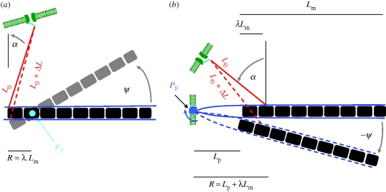
Although ferrimagnetic material appears suitable as a basis of magnetic field perception in animals, it is not known by which mechanism magnetic particles may transduce the magnetic field into a nerve signal. Provided that magnetic particles have remanence or anisotropic magnetic susceptibility, an external magnetic field will exert a torque and may physically twist them. Several models of such biological magnetic-torque transducers on the basis of magnetite have been proposed in the literature. We analyse from first principles the conditions under which they are viable. Models based on biogenic single-domain magnetite prove both effective and efficient, irrespective of whether the magnetic structure is coupled to mechanosensitive ion channels or to an indirect transduction pathway that exploits the strayfield produced by the magnetic structure at different field orientations. On the other hand, torque-detector models that are based on magnetic multi-domain particles in the vestibular organs turn out to be ineffective. Also, we provide a generic classification scheme of torque transducers in terms of axial or polar output, within which we discuss the results from behavioural experiments conducted under altered field conditions or with pulsed fields. We find that the common assertion that a magnetoreceptor based on single-domain magnetite could not form the basis for an inclination compass does not always hold.


Figures

Figure 1.
Figure 1.
Equilibrium deflection 〈ψ〉 of an elastically coupled permanent magnet as a function of the orientation θ0 of the external field with respect to the rest orientation of the magnet ψ = 0, for various values of mH and K. Ratio mH/K increases from (a) to (e). Solid line, 〈ψ〉, thermal equilibrium value of deflection (equation (C 2)); grey area, angular scatter ±Δψ about 〈ψ〉 (equation (C 4)); blue dashed line, mechanical equilibrium value of deflection ψ; red dotted line, approximate mechanical equilibrium deflection according to equation (3.4a) in (a,b) and equation (3.4b) in (c). Note the strong increase in angular scatter on going towards the antiparallel field orientation (θ0 = 180°) once mH/K ∼1, in (d) and particularly in (e). (f) Zoom-in on the unstable region in (e). (a) mH = 25kT, K = 300kT; (b) mH = 50kT, K = 300kT; (c) mH = 25kT, K = 50kT; (d) mH = 25kT, K = 25kT; (e) mH = 25kT, K = 15kT.
Figure 2.
Figure 2.
Amplitude of the angular scatter produced by thermal fluctuations as a function of the ratio of magnetic energy mH to elastic rigidity K for various values of K. Solid lines, Δψ(θ0 = 180°), i.e. angular scatter about the equilibrium position when the field is antiparallel to the rest orientation of the magnet, calculated according to equation (D 3b). Dashed lines, angular scatter Δψ(θ0 = 0) for the parallel orientation (equation (D 3a)).
Figure 3.
Figure 3.
Indirect torque-transducer mechanism according to Binhi (2006). (a) Equilibrium deflection ψ(180° − η) of the magnet for a field orientation θ0 = 180° − η close to the critical orientation θ0 = 180° (i.e. η is a few degrees). (b) As θ0 changes from 180° − η to 180°, the magnet suddenly recoils to the +ψ± orientation. This way, a small change in external field direction can produce a large change in the magnet's deflection, hence a large change in the magnet's strayfield Hs at the site (green patch) where free-radical reactions are assumed to transduce the strayfield into a nerve signal. Thermal fluctuations can drive the magnet from its pre-critical ψ(180° − η) orientation also into the metastable −ψ± orientation (dotted arrow). If the energy barriers between the +ψ± and the −ψ± state are of the order of the thermal energy, the magnet will repeatedly bounce between the +ψ± and −ψ± state.
Figure 4.
Figure 4.
Relative reduction r(H; m, K) of strayfield intensity (equation (3.7)) produced by a magnet at a free-radical reaction site on moving from θ0 = 180° − η to 180° (compare figure 3). The magnetic moment of the magnet is fixed (25kT/Oe); the values of K range from 5 to 12.5kT/rad (colours). Dashed lines, r(H; m, K) calculated from equations (D 7) and (D 8) (see also Binhi 2006). Solid lines, r(H; m, K) calculated from equation (D 9).
Figure 5.
Figure 5.
Sketch of mechanosensitive transduction pathway with geometrical parameters used for theoretical modelling (not to scale). A magnetosome chain, which can be deflected about a pivot (stiffness Kp), is connected through a filament to a force-gated ion channel. The orientation ψ = 0 defines the orientation of the chain where no elastic torque acts on the pivotal spring. (a) The torsional pivot PT is oriented perpendicular to the plane defined by the magnet and the gating filament. The pivot is attached to the chain at a distance R = λLm from the end where the gating filament is inserted. The anchor point P1 of the gating filament lies on the circle defined by P1 = −R(cos ψ, sin ψ). The other end of the gating filament is attached to a force-gated ion channel in the cell membrane at position P2 = (−RL0 sin α, L0 cos α). (b) The gating filament is anchored to the magnet at a distance R = Lp + λLm, where Lm is the length of the magnet and λ is a fraction of Lm. The anchor point P1 lies on the circle defined by P1 = R(cos ψ, sin ψ). The other end of the gating filament spring is attached to a force-gated ion channel in the cell membrane at position P2 = (R L0 sin α, L0 cos α). In (a,b), ΔL(ψ) is the change in the Euclidian distance between P2 and P1 as the chain is deflected by an angle ψ. For small angles, ΔL(ψ) can be approximated as arc length.
Figure 6.
Figure 6.
Opening probability of a force-gated ion channel as a function of the orientation of the external field for three different values of the magnetic to thermal energy ratio (olive, mH = 5kT; magneta, mH = 15kT; blue, mH = 45kT). Parameters: stiffness Kp of the pivot 100kT/rad, effective lever arm and R cos α = 50 nm, i.e. Keff = 390kT/rad.

References

    1. Bazylinski D. A., Schlezinger D. R., Howes B. H., Frankel R. B., Epstein S. S. 2000. Occurrence and distribution of diverse populations of magnetic protists in a chemically stratified coastal salt pond. Chem. Geol. 169, 319–328. ( 10.1016/S0009-2541(00)00211-4) - DOI
    1. Beason R. C., Wiltschko R., Wiltschko W. 1997. Pigeon homing: effects of magnetic pulses on initial orientation. Auk 114, 405–415.
    1. Binhi V. N. 2006. Stochastic dynamics of magnetosomes and a mechanism of biological orientation in the geomagnetic field. Bioelectromagnetics 27, 58–63. ( 10.1002/bem.20178) - DOI - PubMed
    1. Blakemore R. P. 1975. Magnetotactic bacteria. Science 190, 377–379. ( 10.1126/science.170679) - DOI - PubMed
    1. Boulbitch A. A. 1998. Deflection of a cell membrane under application of a local force. Phys. Rev. E 57, 2123–2128. ( 10.1103/PhysRevE.57.2123) - DOI