Review
. 2010;94(1):1-18.
doi: 10.1002/bip.21328.

Self-assembly of peptide amphiphiles: from molecules to nanostructures to biomaterials

Affiliations
Review

Self-assembly of peptide amphiphiles: from molecules to nanostructures to biomaterials

Honggang Cui et al. Biopolymers. 2010.

Abstract

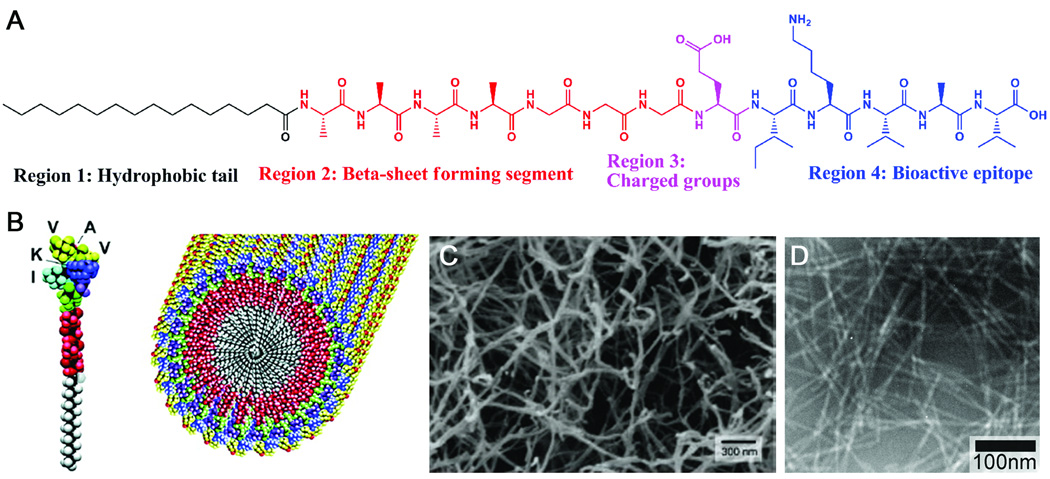
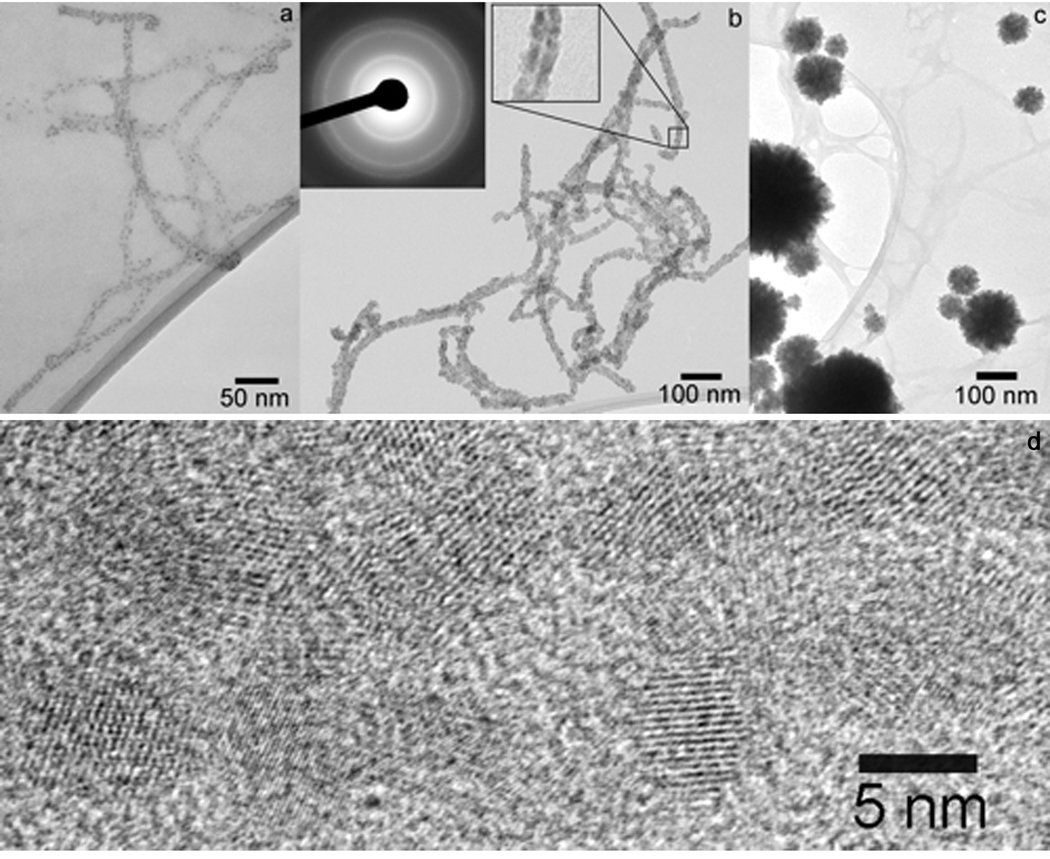
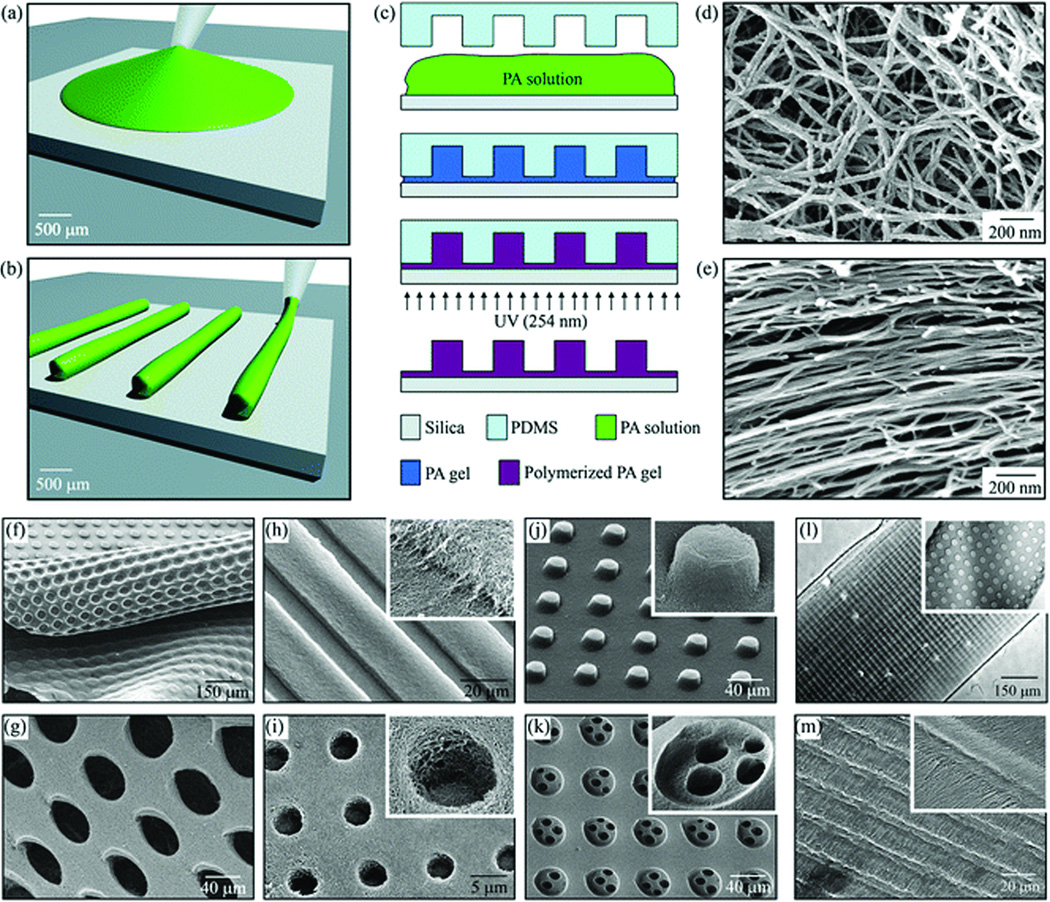
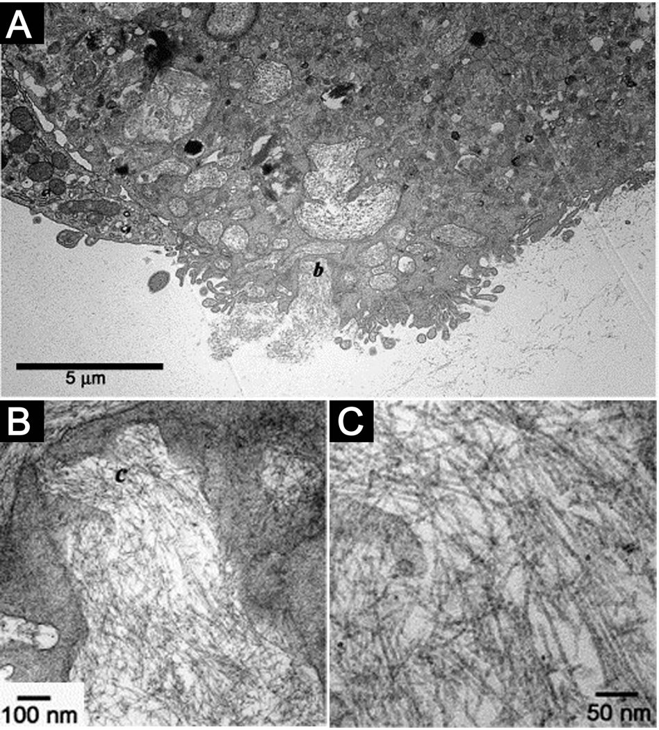
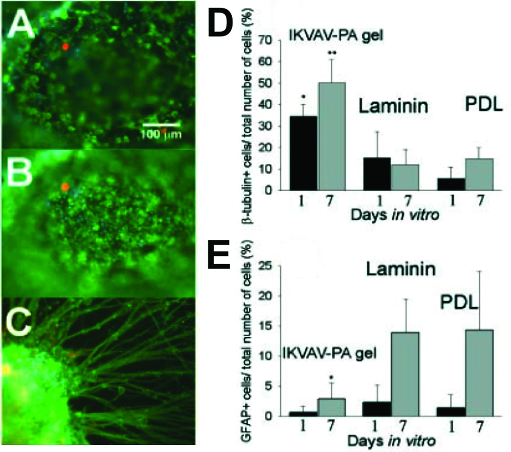
Peptide amphiphiles are a class of molecules that combine the structural features of amphiphilic surfactants with the functions of bioactive peptides and are known to assemble into a variety of nanostructures. A specific type of peptide amphiphiles are known to self-assemble into one-dimensional nanostructures under physiological conditions, predominantly nanofibers with a cylindrical geometry. The resultant nanostructures could be highly bioactive and are of great interest in many biomedical applications, including tissue engineering, regenerative medicine, and drug delivery. In this context, we highlight our strategies for using molecular self-assembly as a toolbox to produce peptide amphiphile nanostructures and materials and efforts to translate this technology into applications as therapeutics. We also review our recent progress in using these materials for treating spinal cord injury, inducing angiogenesis, and for hard tissue regeneration and replacement.


Figures

Figure 1
Figure 1
(A) Molecular Structure of a representative peptide amphiphile with four rationally designed chemical entities. (B) Molecular graphics illustration of an IKVAV-containing peptide amphiphile molecule and its self-assembly into nanofibers; (C) Scanning electron micrograph of the IKVAV nanofiber network formed by adding cell media (DMEM) to the peptide amphiphile aqueous solution; (D) Transmission electron micrograph of the IKVAV nanofibers,.
Figure 2
Figure 2
Schematic phase diagram of peptide amphiphile assemblies. The phase diagram includes regions with (a) free molecules, (b) spherical micelles, (c) micelles with β-sheets on the outside forming the corona, (d) long cylindrical fibers, (e) stacks of parallel sheets, (f) single β-sheets, and (g) the amorphous aggregate phase.
Figure 3
Figure 3
Giant (ultralong and wide) nanobelts assembled from a peptide amphiphile containing four amino acids and an alkyl tail. (a) Chemical structure of the peptide amphiphile. (b–d) AFM images of peptide nanobelts at different scanning sizes. The assembled nanobelts are the dominant structures in the assembly system (almost artifact free). (e and f) AFM images of a single-layer and a double-layer nanobelt morphology. (g) AFM amplitude image of (f). (h) CD spectrum of the peptide nanobelt solution at a concentration of 0.05 wt % proves the existence of β-sheet secondary structure in the supramolecular assemblies.
Figure 4
Figure 4
(A) Schematic representation of one method to form a self-sealing closed sac. A sample of the denser negatively charged biopolymer solution is dropped onto a positively charged peptide amphiphile solution. (B) Open and (C) closed sac formed by injection of a fluorescently tagged hyaluronic acid solution into a PA solution. (D) Self-assembled sacs of varying sizes. (E) PA-HA membranes of different shapes created by interfacing the large- and small-molecule solutions in a very shallow template (~1 mm thick). (F) Continuous strings pulled from the interface between the PA and HA solutions.
Figure 5
Figure 5
Bright field TEM micrographs of CdS mineralized suspensions of PA fibers at various Cd2+:PA molar ratio. (a) Cd2+:PA = 2.4:1; (b) Cd2+:PA = 24:1. Left inset shows an electron diffraction pattern corresponding to the CdS zinc blende structure. Right inset shows an enlargement of a portion of an encapsulated fiber highlighting the strip of lower electron density through the middle corresponding to the hydrophobic core. (c) Cd2+:PA = 240:1. (d) High-resolution TEM micrograph showing the lattice structure of CdS nanocrystals grown on a PA fiber. Fiber axis is parallel to the long axis of the micrograph.
Figure 6
Figure 6
Fabrication techniques and resulting PA structures. (a–e) The fabrication process starts by either (a) dropping freshly dissolved PA for microtextures with randomly oriented nanofibers, or (b) dragging an aged PA solution for microtextures with aligned nanofibers on a silica substrate. (c) Then, a PDMS mold was used to cover the PA solution while allowing it to conform to the mold, self-assemble into nanofibers, and gel by exposure to ammonium hydroxide (NH4OH). The PA gel was then polymerized under UV irradiation and released from the mold to realize the PA microtextures. The process in (a,c) was used to achieve well-defined three-dimensional PA structures with (d) randomly oriented nanofibers including (f) removable layers with microtextures or (g) pores and surface microtextures such as (g) channels, (i) holes, (j) posts, and (k) two-level topographies with features down to 5 µm in size. On the other hand, following the process in (b,c), microtextures with (l,m) channels and holes were also achieved but with aligned nanofibers (inset in m).
Figure 7
Figure 7
(A) TEM micrograph of a cell entrapped in the nanofibrillar matrix internalizing the PA nanofibers. (B) Intermediate magnification of the region marked b in (A) showing the formation of intracellular membrane delineated compartments filled with nanofibers. (C) High magnification micrograph of the nanofibers in the area marked c in (B).
Figure 8
Figure 8
Neural Progenitor Cells (NPCs) cultured under different experimental conditions. (A and B) The same field of view in two different planes of focus showing immunocytochemistry of NPCs encapsulated in IKVAV-PA gels at 1 day. Differentiated neurons were labeled for β-tubulin (in green) and differentiated astrocytes (glial cells) were labelled for GFAP (in orange). All cells were Hoechst stained (in blue). (C) Immunocytochemistry of an NPC neurosphere encapsulated in an IKVAV-PA nanofiber network at 7 days. The large extent of neurite outgrowth was typical of the cells examined. (D) Percentage of total cells that differentiated into neurons (β-tubulin+). The IKVAV-PA gels had significantly more neurons compared to both laminin and poly-D-lysine (PDL) controls at both 1 and 7 days (*P<0.05, **P<0.01). (E) Percentage of total cells that differentiated into astrocytes (GFAP+). The IKVAV-PA gels had significantly fewer astrocytes compared to both laminin and PDL controls by 7 days (*P<0.05).
Figure 9
Figure 9
Branched RGD-peptide amphiphiles (BRGD-PA) influencing ameloblast cell behaviour after injection into the enamel organ epithelia (solid arrow) of incisor primordial maintained for 2 days in organ culture. The complete incisor is shown at low power in A, B, and C with the injection site marked by a dashed line box. (A–G) Higher-magnification images of representative tissue sections from the site of injection (solid arrow). Od, odontoblasts; Am, ameloblasts; SI, stratum intermedium. A–D show cell proliferation using BrdU incorporation into cellular DNA. The stem cell compartment at the caudal end of the incisor is marked with an open arrow and corresponds to sites of high cell division. (A) Sham treatment consisting of incisor primordia injected with PBS showed little BrdU incorporation into the DNA of enamel organ epithelial cells at the injection site. (B) Incisor primordia injected with control PA showed but a few BrdU-labelled cells at the injection site. (C) Incisor primordia injected with BRGD-PA showed cells have incorporated BrdU as a consequence of increased cell division. (D) Bar graph of the total number of cells incorporating BrdU from the injections sites shown in A–C. (E–G) Immunodetection of integrin 6 protein expression from representative sections taken from incisor primordia at the site of PA injection (solid arrow). (E) Relatively low levels of integrin 6 protein expression localized to enamel organ cells and part of dental papillae in sham treated incisor primordia. (F) Integrin 6 protein expression at the injection site of the control-PA. (G) Increased integrin 6 protein expression among the cells at the injection site of the BRGD-PA. The cells at the injected site are shown to be proliferating in C.
Figure 10
Figure 10
In vivo angiogenesis assay. Rat cornea photographs 10 days after the placement of various materials at the site indicated by the black arrow. Heparin-nucleated PA nanofiber networks with growth factors show extensive neovascularization. Controls of collagen, heparin, and growth factors (B) and collagen with growth factors (C) show some neovascularization. Heparin with growth factors (D), and collagen with heparin. The bar graph (F) contains values for the average and maximum length of new blood vessels and the area of corneal neovascularization. A 100% value in the area measurement indicates that the cornea is completely covered, and a 100% value in the length parameters indicates that the new vessels are as long as the diameter of the cornea (bars are 95% confidence levels, * p < 0.05 when PA-heparin gel was compared to collagen gel with growth factors, ** p < 0.005 when PA-heparin gel with growth factors was compared to all of the other controls). PA nanofibers with heparin, PA solution with growth factors, and growth factors alone did not result in measurable neovascularization (values not shown in graph).

Similar articles

Cited by

References

    1. Palmer LC, Stupp SI. Accounts of Chemical Research. 2008;41:1674–1684. - PMC - PubMed
    1. Palmer LC, Velichko YS, de la Cruz MO, Stupp SI. Philosophical Transactions of the Royal Society a-Mathematical Physical and Engineering Sciences. 2007;365:1417–1433. - PubMed
    1. Stupp SI, Pralle MU, Tew GN, Li LM, Sayar M, Zubarev ER. Mrs Bulletin. 2000;25:42–48.
    1. Service RF. Science. 2005;309:95–95. - PubMed
    1. Hartgerink JD, Zubarev ER, Stupp SI. Current Opinion in Solid State & Materials Science. 2001;5:355–361.

Publication types

LinkOut - more resources