. 2009 Dec;36(12):5707-18.
doi: 10.1118/1.3259721.

High-DQE EPIDs based on thick, segmented BGO and CsI:Tl scintillators: performance evaluation at extremely low dose

Affiliations

High-DQE EPIDs based on thick, segmented BGO and CsI:Tl scintillators: performance evaluation at extremely low dose

Yi Wang et al. Med Phys. 2009 Dec.

Abstract

Purpose: Electronic portal imaging devices (EPIDs) based on active matrix, flat-panel imagers (AMFPIs) have become the gold standard for portal imaging and are currently being investigated for megavoltage cone-beam computed tomography (CBCT) and cone-beam digital tomosynthesis (CBDT). However, the practical realization of such volumetric imaging techniques is constrained by the relatively low detective quantum efficiency (DQE) of AMFPI-based EPIDs at radiotherapy energies, approximately 1% at 6 MV. In order to significantly improve DQE, the authors are investigating thick, segmented scintillators, consisting of 2D matrices of scintillating crystals separated by septal walls.

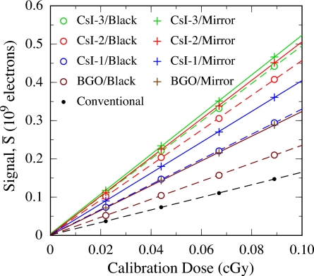
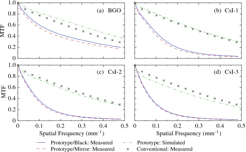
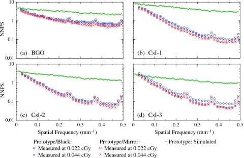
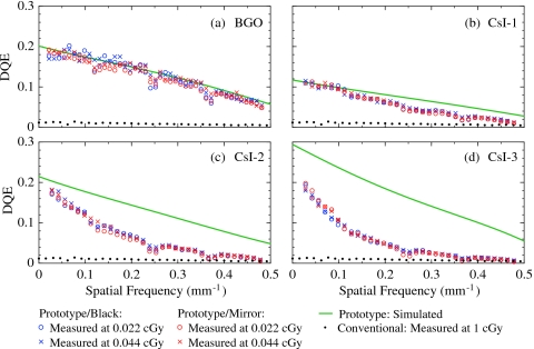
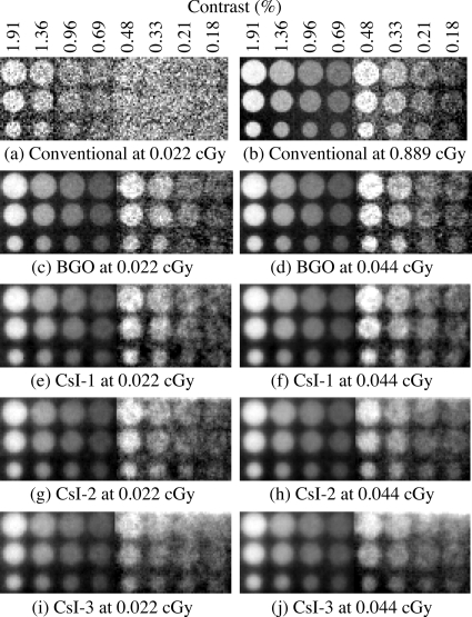
Methods: A newly constructed segmented BGO scintillator (11.3 mm thick) and three segmented CsI:Tl scintillators (11.4, 25.6, and 40.0 mm thick) were evaluated using a 6 MV photon beam. X-ray sensitivity, modulation transfer function, noise power spectrum, DQE, and phantom images were obtained using prototype EPIDs based on the four scintillators.

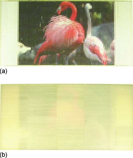
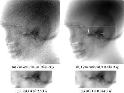
Results: The BGO and CsI:Tl prototypes were found to exhibit improvement in DQE ranging from approximately 12 to 25 times that of a conventional AMFPI-based EPID at zero spatial frequency. All four prototype EPIDs provide significantly improved contrast resolution at extremely low doses, extending down to a single beam pulse. In particular, the BGO prototype provides contrast resolution comparable to that of the conventional EPID, but at 20 times less dose, with spatial resolution sufficient for identifying the boundaries of low-contrast objects. For this prototype, however, the BGO scintillator exhibited an undesirable radiation-induced variation in x-ray sensitivity.

Conclusions: Prototype EPIDs based on thick, segmented BGO and CsI:T1 scintillators provide significantly improved portal imaging performance at extremely low dose (i.e., down to 1 beam pulse corresponding to approximately 0.022 cGy), creating the possibility of soft-tissue visualization using MV CBCT and CBDT at clinically practical dose.


Figures

Figure 1
Figure 1
Pictures showing a top view of the segmented (a) BGO (11.3 mm thick) and (b) CsI-1 (11.4 mm thick) scintillators overlying the same photograph of two flamingos. Note that the photograph is narrower than the scintillators. The light grid of the horizontal and vertical lines corresponds to the septal walls of the prototypes. The BGO scintillator is seen to be more transparent than the CsI-1 scintillator. Also note that the BGO and CsI-1 scintillators were assembled from seven and five subassemblies (each consisting of 60 rows of elements), respectively. Although the transparencies of the various subassemblies are very similar for the BGO prototype, this is not the case for the CsI-1 prototype.
Figure 2
Figure 2
Average signal per binned pixel as a function of calibration dose for the four prototype EPIDs. Results for each prototype, configured with the black top reflector (open circles) and with the mirror top reflector (plus symbols), are shown. (Note that, for a given type of reflector, the legend is organized, from top to bottom, in order of decreasing prototype sensitivity). For comparison, the average signal for the conventional EPID is also plotted (black dots). The dashed lines (which correspond to results with the black reflector and the conventional EPID) and solid lines (which correspond to results with the mirror reflector) are linear fits to the data.
Figure 3
Figure 3
Presampled modulation transfer function (MTF) for the (a) BGO, (b) CsI-1, (c) CsI-2 and (d) CsI-3 prototype EPIDs. The results are shown for configurations with the black top reflector (blue lines) and the mirror top reflector (red dashed lines). The maximum estimated error in these MTF results is ∼3%. The green dot-dashed lines correspond to the MTF obtained from simulation of the various prototypes. The black crosses correspond to MTF results measured from the conventional EPID (adapted from data appearing in Ref. 2).
Figure 4
Figure 4
NNPS for the (a) BGO, (b) CsI-1, (c) CsI-2, and (d) CsI-3 prototype EPIDs. The results are shown for configurations with the black top reflector (blue symbols) and the mirror top reflector (red symbols), at both 0.022 and 0.044 cGy. The maximum estimated error in the NPS results is ∼5%. The green dots correspond to simulated NNPS for the prototype EPIDs.
Figure 5
Figure 5
DQE for the (a) BGO, (b) CsI-1, (c) CsI-2, and (d) CsI-3 prototype EPIDs. The results are shown for configurations with the black top reflector (blue symbols) and the mirror top reflector (red symbols), at both 0.022 and 0.044 cGy. The maximum estimated error in these DQE results is ∼7%. The green lines correspond to polynomial fits to the DQE results obtained through simulation. The black dots correspond to DQE results measured from the conventional EPID at 1 cGy (adapted from data appearing in Ref. 2).
Figure 6
Figure 6
X-ray images of a contrast-detail phantom. Images acquired using the conventional EPID at (a) 0.022 and (b) 0.889 cGy. Images acquired using the (c) BGO, (e) CsI-1, (g) CsI-2, and (i) CsI-3 prototypes at 0.022 cGy; and the (d) BGO, (f) CsI-1, (h) CsI-2, and (j) CsI-3 prototypes at 0.044 cGy. All prototype EPIDs were configured with a mirror top reflector. Due to the limited size of the segmented scintillators, each image is formed by stitching two separately acquired images (left and right) corresponding to adjacent parts of the phantom. In addition, in order to optimize object visibility, the two images were enhanced separately using different windows and levels. For consistency, the same image enhancement method was applied to the corresponding parts of the images acquired with the conventional EPID. The legend above (a) and (b) indicate the estimated contrast of the holes at 6 MV (Ref. 37). The diameters of the three rows of holes are 1.3, 0.8, and 0.5 cm.
Figure 7
Figure 7
X-ray images of a human head phantom acquired using the conventional EPID at (a) 0.044 and (b) 0.444 cGy, and the BGO prototype (with the mirror top reflector) at (c) 0.022 and (d) 0.044 cGy. The white rectangle superimposed in (b) corresponds to the region imaged by the BGO prototype, while the two white arrows point to a pair of low-contrast features.

References

    1. Antonuk L. E., “Electronic portal imaging devices: A review and historical perspective of contemporary technologies and research,” Phys. Med. Biol. PHMBA7 47, R31–R65 (2002).10.1088/0031-9155/47/2/401 - DOI - PubMed
    1. El-Mohri Y., Jee K. -W., Antonuk L. E., Maolinbay M., and Zhao Q., “Determination of the detective quantum efficiency of a prototype, megavoltage indirect detection, active matrix flat-panel imager,” Med. Phys. MPHYA6 28, 2538–2550 (2001).10.1118/1.1413516 - DOI - PubMed
    1. Antonuk L. E., Jee K. -W., El-Mohri Y., Maolinbay M., Nassif S., Rong X., Zhao Q., Siewerdsen J. H., Street R. A., and Shah K. S., “Strategies to improve the signal and noise performance of active matrix, flat-panel imagers for diagnostic x-ray applications,” Med. Phys. MPHYA6 27, 289–306 (2000).10.1118/1.598831 - DOI - PubMed
    1. El-Mohri Y., Antonuk L. E., Zhao Q., Wang Y., Li Y., Du H., and Sawant A., “Performance of a high fill factor, indirect detection prototype flat-panel imager for mammography,” Med. Phys. MPHYA6 34, 315–327 (2007).10.1118/1.2403967 - DOI - PubMed
    1. Granfors P. R., Aufrichtig R., Possin G. E., Giambattista B. W., Huang Z. S., Liu J., and Ma B., “Performance of a 41×41 cm2 amorphous silicon flat panel x-ray detector designed for angiographic and R&F imaging applications,” Med. Phys. MPHYA6 30, 2715–2726 (2003).10.1118/1.1609151 - DOI - PubMed

Publication types