. 2009 Feb 1;6(2):145.
doi: 10.1007/s10404-008-0399-9.

Electroosmotic pumps and their applications in microfluidic systems

Affiliations

Electroosmotic pumps and their applications in microfluidic systems

Xiayan Wang et al. Microfluid Nanofluidics. .

Abstract

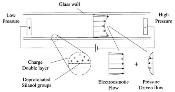
Electroosmotic pumping is receiving increasing attention in recent years owing to the rapid development in micro total analytical systems. Compared with other micropumps, electroosmotic pumps (EOPs) offer a number of advantages such as creation of constant pulse-free flows and elimination of moving parts. The flow rates and pumping pressures of EOPs matches well with micro analysis systems. The common materials and fabrication technologies make it readily integrateable with lab-on-a-chip devices. This paper reviews the recent progress on EOP fabrications and applications in order to promote the awareness of EOPs to researchers interested in using micro- and nano-fluidic devices. The pros and cons of EOPs are also discussed, which helps these researchers in designing and constructing their micro platforms.


Figures

Fig. 1
Fig. 1
Schematic illustration of electric double layer and principle of EO flow. In EOF, mobile ions in the diffuse counter-ion layer of the electric double layer are driven by an externally applied electrical field. These moving ions drag along bulk liquid through viscous force interaction. The net flow is the superposition of EOF and pressure forces. Reprinted with permission from Chen and Santiago 2002
Fig. 2
Fig. 2
Schematic diagram of AC electroosmotic flow in a symmetric electrode array. Surface slip at electrodes, and resulting fluid streamlines are represented with solid and broken lines, respectively. Reprinted with permission from Urbanski et al. 2006
Fig. 3
Fig. 3
Schematic diagram of AC electroosmotic flow in an asymmetric electrode array. The asymmetry leads to fluid rolls of different sizes over each electrode resulting in a net fluid flow. Reprinted with permission from Ramos et al. 2003
Fig. 4
Fig. 4
Schematic diagram of AC electroosmotic flow in a 3D stepped electrode array. Surface slip at electrodes, and resulting fluid streamlines are represented with solid and broken lines, respectively. Reprinted with permission from Urbanski et al. 2006
Fig. 5
Fig. 5
Schematic diagram of an stand-alone EOP: a schematic configuration of an stand-alone EOP; b detailed structure of a membrane joint. A Pump electrolyte container; B vial housing M and containing the same solution as A; HV high-voltage power supply; C1 pumping capillary; M membrane; V1 four-way valve; S1 and S2 syringes respectively holding pump buffer solution and reagent solutions; HC reagent holding coil. Reprinted with permission from Dasgupta and Liu 1994
Fig. 6
Fig. 6
Open-channel EOP. 1 Open-channel EOP, 2 micropump inlet reservoir, and 3 micropump outlet reservoir. The bottom figure shows an expanded view of reservoir 3 containing the porous glass disk. Reprinted with permission from Lazar and Karger 2002
Fig. 7
Fig. 7
Photograph of fabricated cascade-type EOP. Reprinted with permission from Takamura et al. 2003
Fig. 8
Fig. 8
Schematic diagram of two-line FIA system with EOF pumping: B, pump electrolyte solution container; T1, T2, capillary unions; Vla and Vlb, four-way valve stacks a and b; S1 and S3, syringes holding pump buffer solution; S2 and S4, syringes respectively holding carrier and reagent solutions; HC, reagent holding coil; T3, low-volume tee union. Reprinted with permission from Dasgupta and Liu 1994
Fig. 9
Fig. 9
Schematic diagram of capillary format SIA system. HV High-voltage power supply; A, B pumping electrolyte solution containers; M membrane joint; C1 pumping capillary; T 4 × 1 union; HC holding coil; V1 four-way valve; S1, S2 syringes; V2 6 × 1 selector valve; R1, R2, R3 reagents; aux, unused auxiliary solution port. Reprinted with permission from Liu and Dasgupta 1994
Fig. 10
Fig. 10
a The photomask design of the pump chip. b Schematic arrangement of the micro-EOP-SIA system. Reprinted with permission from Pu and Liu 2004
Fig. 11
Fig. 11
Schematic diagram of the one-stage EOP and the μ-HPLC system. a The EOP system: 1 solvent reservoir, covered with an insulating sheath; 2 high-voltage direct current source module; 3 Pt wire; 4 hollow electrode (grounded); 5 capillary conduit; 6 packed columns, three packed columns connected in parallel; 7 gas releasing device (8 representation of gas leaving direction); 9 liquid pressure sensor; 10 open/close valve; 11 measurement point of flow rate. b The μ-HPLC system: 12 a four-port injection valve; 13 analytical capillary HPLC column; 14 an on-column UV—Vis detector; 15 chromatographic data station; 16 waste liquid bottle. Reprinted with permission from Chen et al. 2004
Fig. 12
Fig. 12
Schematic representation of a microfluidic LC system. 1 Pumping channels; 2A, 2B eluent inlet reservoirs; 3 eluent outlet reservoir; 4 double-T injector that contains the sample plug; 5 separation channel; 6 sample reservoir; 7 sample waste reservoir; 8 sample inlet channels; 9 sample outlet channels; 10 ESI capillary emitter; 11 LC waste reservoir. a Sample loading; b sample analysis. Arrows indicate the main flow pattern through the system. Reprinted with permission from Lazar et al. 2006

References

    1. Ajdari A. Pumping liquids using asymmetric electrode arrays. Phys Rev E. 2000;61(1):R45–R48. - PubMed
    1. Aoki H, Kubo T, Ikegami T, Tanaka N, Hosoya K, Tokuda D, Ishizuka N. Preparation of glycerol dimethacrylate-based polymer monolith with unusual porous properties achieved via viscoelastic phase separation induced by monodisperse ultra high molecular weight poly(styrene) as a porogen. J Chromatogr A. 2006;1119(1–2):66–79. - PubMed
    1. Bazant MZ, Ben Y. Theoretical prediction of fast 3D AC electro-osmotic pumps. Lab Chip. 2006;6(11):1455–1461. - PubMed
    1. Berrouche Y, Avenas Y, Schaeffer C, Wang P, Chang H-C. Optimization of high flow rate nanoporous electroosmotic pump. J Fluids Eng. 2008;130(8):081604/1–081604/6.
    1. Berthelot M. Violet d’aniline. Rep Chim Appl. 1859;1:284.

LinkOut - more resources