. 2010 Feb;5(2):201-8.
doi: 10.1038/nprot.2009.222. Epub 2010 Jan 14.

Thinned-skull cranial window technique for long-term imaging of the cortex in live mice

Affiliations

Thinned-skull cranial window technique for long-term imaging of the cortex in live mice

Guang Yang et al. Nat Protoc. 2010 Feb.

Abstract

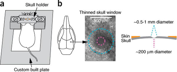
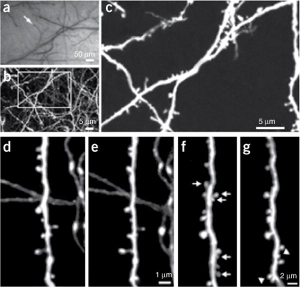
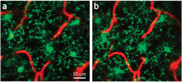
Imaging neurons, glia and vasculature in the living brain has become an important experimental tool for understanding how the brain works. Here we describe in detail a protocol for imaging cortical structures at high optical resolution through a thinned-skull cranial window in live mice using two-photon laser scanning microscopy (TPLSM). Surgery can be performed within 30-45 min and images can be acquired immediately thereafter. The procedure can be repeated multiple times allowing longitudinal imaging of the cortex over intervals ranging from days to years. Imaging through a thinned-skull cranial window avoids exposure of the meninges and the cortex, thus providing a minimally invasive approach for studying structural and functional changes of cells under normal and pathological conditions in the living brain.


Figures

Figure 1
Figure 1
Schematic diagram of thinned-skull preparation. (a) A head immobilization device including a custom built plate and a skull holder is used for reducing movement artifacts during imaging. The skull holder is glued on the mouse skull and tightened on the aluminum blocks of the custom built plate. The region of interest is exposed in the center. (b) A circular area of skull (typically ~0.5–1 mm in diameter, marked with blue circle) over the region of interest is shaved. The thinnest region (marked with pink circle) for two-photon laser scanning microscopy (TPLSM) imaging is ~20 μm in thickness and ~200 μm in diameter. All experiments using animals were carried out under the institutional and national guidelines.
Figure 2
Figure 2
Long-term transcranial two-photon laser scanning microscopy (TPLSM) imaging of fine neuronal structures. (a) CCD camera view of the brain vasculature under the thinned skull. The cortical vasculature can be clearly seen through the thinned skull. The vasculature pattern remains stable over months to years and can be used as a landmark to relocate the imaged region at subsequent time points. Arrow indicates the region where subsequent TPLSM images were obtained. (b) Two dimensional projection of a 3D stack of dendritic branches and axons in the primary visual cortex (×60, ~0.39 μm pixel− 1). The stack was 50 μm deep (2 μm step size). The boxed region was then imaged at higher magnification. (c) High power 2D projection of a 3D stack (×60, ~0.13 μm pixel− 1, 10 μm reconstructed, 0.70 μm step size) reveals clear neuronal structures including axonal varicosities, dendritic shafts and dendritic protrusions. (d,e) Axonal and dendritic branches from two animals imaged 3-d apart show the same spines and boutons at the same locations (adapted from reference 2). (f,g) Dendritic branches imaged over 19 months apart. The arrows indicate spines that are eliminated in the second view. The arrowheads indicate spines that are formed in the second view. Note that most spines in f persist in g (adapted from reference 10). Two-dimensional projections of three-dimensional image stacks containing dendritic segments of interest were used for dg. Scale bar: 50 μm (a), 5 μm (b,c), 1 μm (e) and 2 μm (g). All experiments using animals were carried out under the institutional and national guidelines.
Figure 3
Figure 3
Transcranial two-photon laser scanning microscopy (TPLSM) imaging of enhanced green fluorescent protein (EGFP) labeled microglia and cortical vasculature. (a,b) Two-dimensional projections of a 3D z-stack from the visual cortex (×40, digital zoom = 1) from a mouse harboring a single copy of the CX3CR1-EGFP allele driving EGFP expression in a subset of myeloid cells including CNS-resident parenchymal microglia imaged 24 h apart. The cortical vasculature has been labeled in red by intravenous injection of a rhodamine–dextran conjugate solution. The stacks are 40 μm in depth (1 μm step size) and are representative of a section of cortex spanning 40–80 μm below the dural surface. EGFP-labeled microglia retain their characteristic highly branched morphology indicative of a resting state. Scale bar: 20 μm. All experiments using animals were carried out under institutional and national guidelines.

Similar articles

Cited by

References

    1. Davalos D, et al. ATP mediates rapid microglial response to local brain injury in vivo. Nat Neurosci. 2005;8:752–758. - PubMed
    1. Grutzendler J, Kasthuri N, Gan WB. Long-term dendritic spine stability in the adult cortex. Nature. 2002;420:812–816. - PubMed
    1. Majewska AK, Newton JR, Sur M. Remodeling of synaptic structure in sensory cortical areas in vivo. J Neurosci. 2006;26:3021–3029. - PMC - PubMed
    1. Nishiyama H, Fukaya M, Watanabe M, Linden DJ. Axonal motility and its modulation by activity are branch-type specific in the intact adult cerebellum. Neuron. 2007;56:472–487. - PMC - PubMed
    1. Stosiek C, Garaschuk O, Holthoff K, Konnerth A. In vivo two-photon calcium imaging of neuronal networks. Proc Natl Acad Sci USA. 2003;100:7319–7324. - PMC - PubMed

Publication types

MeSH terms

Substances