Review
. 2010 Jul;31(5):722-30.
doi: 10.1097/MAO.0b013e3181d279e0.

Consensus panel on a cochlear coordinate system applicable in histologic, physiologic, and radiologic studies of the human cochlea

Affiliations
Review

Consensus panel on a cochlear coordinate system applicable in histologic, physiologic, and radiologic studies of the human cochlea

Berit M Verbist et al. Otol Neurotol. 2010 Jul.

Abstract

Hypothesis: An objective cochlear framework, for evaluation of the cochlear anatomy and description of the position of an implanted cochlear implant electrode, would allow the direct comparison of measures performed within the various subdisciplines involved in cochlear implant research.

Background: Research on the human cochlear anatomy in relation to tonotopy and cochlear implantation is conducted by specialists from numerous disciplines such as histologists, surgeons, physicists, engineers, audiologists, and radiologists. To allow accurate comparisons between and combinations of previous and forthcoming scientific and clinical studies, cochlear structures and electrode positions must be specified in a consistent manner.

Methods: Researchers with backgrounds in the various fields of inner ear research as well as representatives of the different manufacturers of cochlear implants (Advanced Bionics Corp., Med-El, Cochlear Corp.) were involved in consensus meetings held in Dallas, March 2005, and Asilomar, August 2005. Existing coordinate systems were evaluated, and requisites for an objective cochlear framework were discussed.

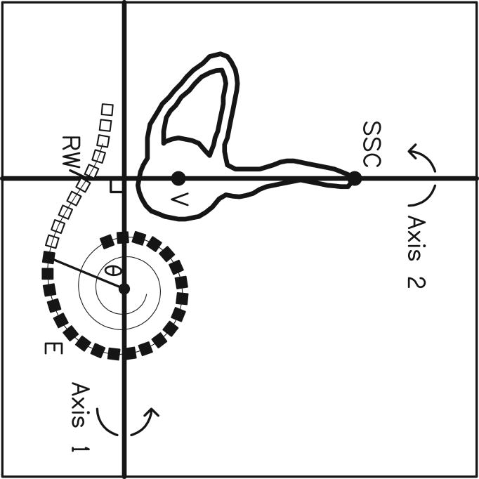
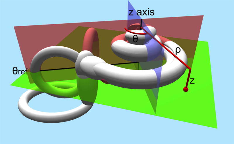
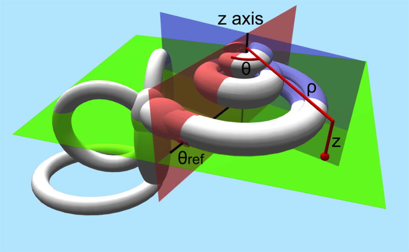
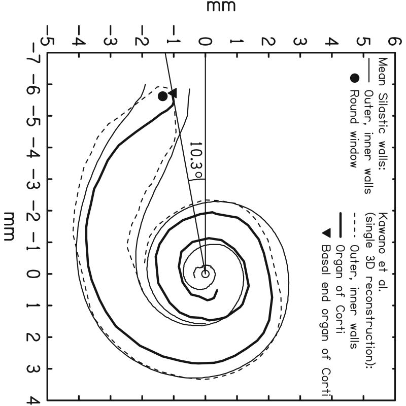
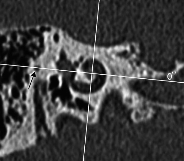
Results: The consensus panel agreed upon a 3-dimensional, cylindrical coordinate system of the cochlea using the "Cochlear View" as a basis and choosing a z axis through the modiolus. The zero reference angle was chosen at the center of the round window, which has a close relationship to the basal end of the Organ of Corti.

Conclusion: Consensus was reached on an objective cochlear framework, allowing the outcomes of studies from different fields of research to be compared directly.


Figures

Fig 1
Fig 1
Schematic drawing of the defined cochlear coordinate system: the plane through the basal turn of the cochlea and perpendicular to the modiolus is chosen as the plane of rotation (green plane). The z-axis is placed through the center of the modiolus (crossing of the red en blue plane), with its origin at the level of the helicotrema. As 0 reference angle (θref) the centre of the round window is chosen (red plane). Measurements will be defined by rotational angle θ and distance to the modiolus ρ.
Fig 2
Fig 2
3D coordinate system according to Washington University in St. Louis: images from the volume render ortho tool in ANALYZE of the body donor's Volume Zoom 3D volume. Upper left panel is a rendering of the 3D volume thresholded to display only bone with the upper turns of the cochlea cut away; it represents the boundary of the fluid/tissue containing spaces that are surrounded by bone. The other 3 panels are gray scale images of the intersecting orthogonal sections for the selected point on the rendered image, marked by the intersection of the yellow and red lines on the rendered image. The green outline in the other 3 panels shows this boundary between bone and fluid/tissue containing spaces. Upper right panel's image is perpendicular to the modiolar axis (light blue dot) and shows the demarcation of the vestibule and the cochlear canal (white line) as well as the zero degree rotation line (light blue line).
Fig 3
Fig 3
CView©: (a) Cochlear View image, (b) schematic drawing of a cochlear coordinate system based upon anatomical landmarks. A reference line is drawn through the superior semicircular canal (SSC) and the centre of the vestibule (V). Based upon Silastic® molds of the scala tympani, inner and outer wall spiral functions were calculated. In addition, from analysis of a temporal bone, a third registered spiral was produced to represent the outer wall of the otic capsule (not shown). This spiral is scaled and shifted on the x-y plane in order to achieve a best fit to the image of the bony outer wall visible on the X-ray, thus determining the centre of the cochlear spiral. A second reference line is drawn from the center point, perpendicular to the first reference line, thus defining a “geometric” zero angle. Kawano's data on the length of the Organ of Corti (OC), superimposed on the figure, enabled estimation of the position of the basal end of the OC (c). This point lay at approximately 10° relative to the “geometric” zero, and was used as the origin for calculation of percentage length along the organ of Corti and, thus, characteristic frequency via the Greenwood equation. (Note, in (b), that although the array tends to penetrate the outer wall of scala tympani, it remains inside the bony outer wall.)
Fig 3
Fig 3
CView©: (a) Cochlear View image, (b) schematic drawing of a cochlear coordinate system based upon anatomical landmarks. A reference line is drawn through the superior semicircular canal (SSC) and the centre of the vestibule (V). Based upon Silastic® molds of the scala tympani, inner and outer wall spiral functions were calculated. In addition, from analysis of a temporal bone, a third registered spiral was produced to represent the outer wall of the otic capsule (not shown). This spiral is scaled and shifted on the x-y plane in order to achieve a best fit to the image of the bony outer wall visible on the X-ray, thus determining the centre of the cochlear spiral. A second reference line is drawn from the center point, perpendicular to the first reference line, thus defining a “geometric” zero angle. Kawano's data on the length of the Organ of Corti (OC), superimposed on the figure, enabled estimation of the position of the basal end of the OC (c). This point lay at approximately 10° relative to the “geometric” zero, and was used as the origin for calculation of percentage length along the organ of Corti and, thus, characteristic frequency via the Greenwood equation. (Note, in (b), that although the array tends to penetrate the outer wall of scala tympani, it remains inside the bony outer wall.)
Fig 4
Fig 4
Angular measurements as performed by Boëx et al: a modified Stenvers (Cochlear View) X-ray is performed (a) and a geometric zero reference was determined by the point at which the electrode array crossed the SSC/V reference line described by Cohen et al and Xu et al. This corresponded approximately to the round window (and differed from the geometric zero of Cohen et al and Xu et al). The line going through this point to the center of the first turn of the spiral made by the electrode array, is used as the zero degree reference line for electrodes belonging to the first turn. For electrodes belonging to the second turn of the spiral of the electrode array a line going through the estimated site of the round window to the center of the second turn of the spiral made by the electrode array, is determined as the 720° line (b).
Fig 4
Fig 4
Angular measurements as performed by Boëx et al: a modified Stenvers (Cochlear View) X-ray is performed (a) and a geometric zero reference was determined by the point at which the electrode array crossed the SSC/V reference line described by Cohen et al and Xu et al. This corresponded approximately to the round window (and differed from the geometric zero of Cohen et al and Xu et al). The line going through this point to the center of the first turn of the spiral made by the electrode array, is used as the zero degree reference line for electrodes belonging to the first turn. For electrodes belonging to the second turn of the spiral of the electrode array a line going through the estimated site of the round window to the center of the second turn of the spiral made by the electrode array, is determined as the 720° line (b).
Fig 5
Fig 5
CT-derived cochlear coordinates: a) a schematic drawing shows that the x,y,z –axes are applied comparable to fig 1. The zero degree reference angle (θref) is however chosen at the top of the horizontal SCC. (b) 1 reformatted CT image out of a stack of images through the cochlea is shown. The x,y-axes are shown in red and blue respectively. The x-axis is positioned through the most lateral point of the horizontal SCC, which serves as the 0°-angle in the 3 coordinate system.
Fig 5
Fig 5
CT-derived cochlear coordinates: a) a schematic drawing shows that the x,y,z –axes are applied comparable to fig 1. The zero degree reference angle (θref) is however chosen at the top of the horizontal SCC. (b) 1 reformatted CT image out of a stack of images through the cochlea is shown. The x,y-axes are shown in red and blue respectively. The x-axis is positioned through the most lateral point of the horizontal SCC, which serves as the 0°-angle in the 3 coordinate system.

References

    1. Greenwood DD. A cochlear frequency-position function for several species--29 years later. J Acoust Soc Am. 1990;87:2592–2605. - PubMed
    1. Greenwood DD. Critical bandwidth and consonance in relation to cochlear frequency-position coordinates. Hear Res. 1991;54:164–208. - PubMed
    1. Greenwood D. Critical Bandwidth and Frequency Coordinates of Basilar Membrane. Journal of the Acoustical Society of America. 1961;33:1344.
    1. Blamey PJ, Dooley GJ, Parisi ES, Clark GM. Pitch comparisons of acoustically and electrically evoked auditory sensations. Hearing Research. 1996;99:139–150. - PubMed
    1. Tong YC, Clark GM. Absolute Identification of Electric Pulse Rates and Electrode Positions by Cochlear Implant Patients. Journal of the Acoustical Society of America. 1985;77:1881–1888. - PubMed

Publication types