

Commissioning of the discrete spot scanning proton beam delivery system at the University of Texas M.D. Anderson Cancer Center, Proton Therapy Center, Houston
- PMID: 20175477
- PMCID: PMC11078095
- DOI: 10.1118/1.3259742
Commissioning of the discrete spot scanning proton beam delivery system at the University of Texas M.D. Anderson Cancer Center, Proton Therapy Center, Houston
Abstract
Purpose: To describe a summary of the clinical commissioning of the discrete spot scanning proton beam at the Proton Therapy Center, Houston (PTC-H).
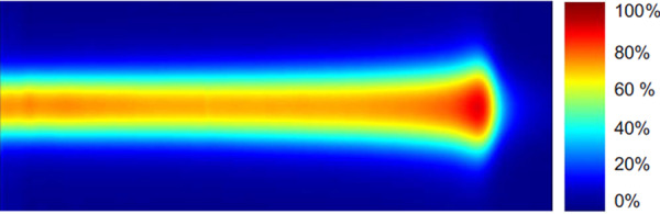
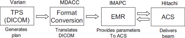
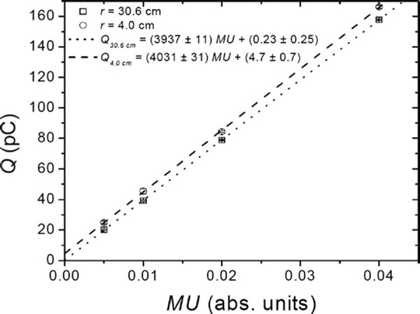
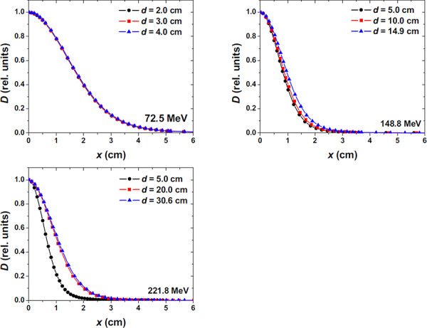
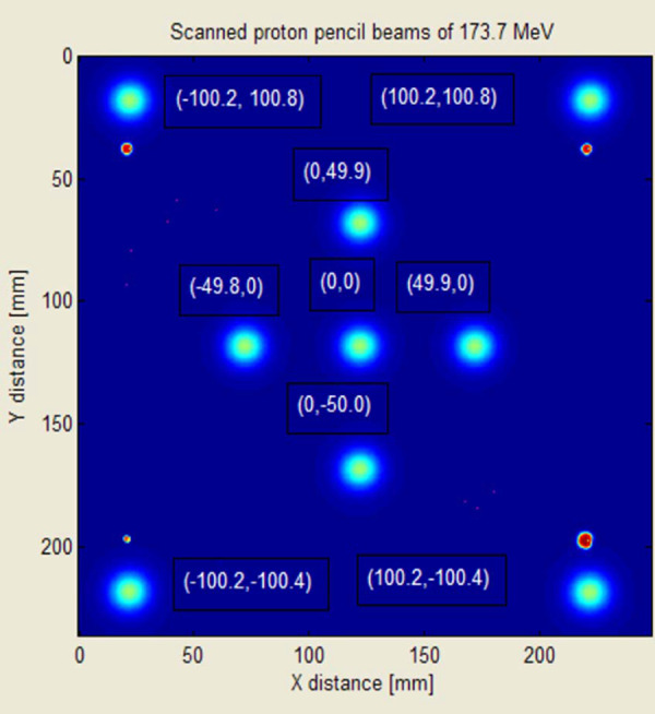
Methods: Discrete spot scanning system is composed of a delivery system (Hitachi ProBeat), an electronic medical record (Mosaiq V 1.5), and a treatment planning system (TPS) (Eclipse V 8.1). Discrete proton pencil beams (spots) are used to deposit dose spot by spot and layer by layer for the proton distal ranges spanning from 4.0 to 30.6 g/cm2 and over a maximum scan area at the isocenter of 30 x 30 cm2. An arbitrarily chosen reference calibration condition has been selected to define the monitor units (MUs). Using radiochromic film and ion chambers, the authors have measured spot positions, the spot sizes in air, depth dose curves, and profiles for proton beams with various energies in water, and studied the linearity of the dose monitors. In addition to dosimetric measurements and TPS modeling, significant efforts were spent in testing information flow and recovery of the delivery system from treatment interruptions.
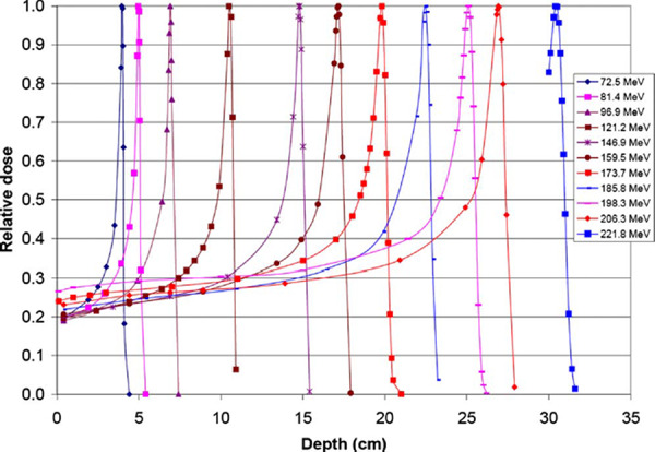
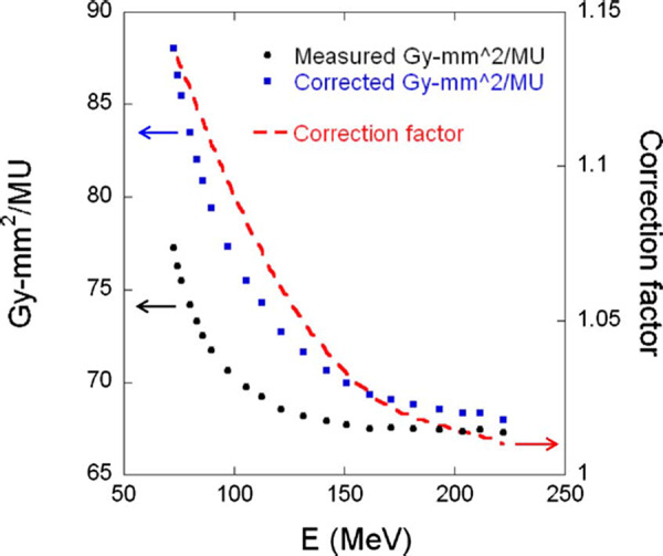
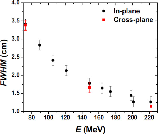
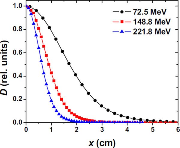
Results: The main dose monitors have been adjusted such that a specific amount of charge is collected in the monitor chamber corresponding to a single MU, following the IAEA TRS 398 protocol under a specific reference condition. The dose monitor calibration method is based on the absolute dose per MU, which is equivalent to the absolute dose per particle, the approach used by other scanning beam institutions. The full width at half maximum for the spot size in air varies from approximately 1.2 cm for 221.8 MeV to 3.4 cm for 72.5 MeV. The measured versus requested 90% depth dose in water agrees to within 1 mm over ranges of 4.0-30.6 cm. The beam delivery interlocks perform as expected, guarantying the safe and accurate delivery of the planned dose.
Conclusions: The dosimetric parameters of the discrete spot scanning proton beam have been measured as part of the clinical commissioning program, and the machine is found to function in a safe manner, making it suitable for patient treatment.
Figures
References
-
- Lomax A. J., Boehringer T., Coray A., Egger E., Goitein G., Grossmann M., Juelke P., Lin S., Pedroni E., Rohrer B., Roser W., Rossi B., Siegenthaler B., Stadelmann O., Stauble H., Vetter C., and Wisser L., “Intensity modulated proton therapy: A clinical example,” Med. Phys. 28, 317–324 (2001). - PubMed
-
- Koehler A. M., Schneider R. J., and Sisterson J. M., “Range modulators for protons and heavy ions,” Nucl. Instrum. Methods 131, 437–440 (1975).
-
- Paganetti H. and Bortfeld T., in New Technologies in Radiation Oncology, edited by Schlegel T. B. W. and Grosu A. L. (Springer‐Verlag, Berlin, 2006), p. 345.
-
- Pedroni E., Bacher R., Blattmann H., Böhringer T., Coray A., Lomax A. J., Lin S., Munkel G., Scheib S., Schneider U., and Tourovsky A., “The proton therapy project at the Paul Scherrer Institute: Conceptual design and practical realization,” Med. Phys. 22, 37–53 (1995). - PubMed
Publication types
MeSH terms
Substances
Grants and funding
LinkOut - more resources
Full Text Sources
Research Materials
