. 2010 Apr 30;285(18):14005-19.
doi: 10.1074/jbc.M109.097717. Epub 2010 Mar 4.

An intersubunit interaction between S4-S5 linker and S6 is responsible for the slow off-gating component in Shaker K+ channels

Affiliations

An intersubunit interaction between S4-S5 linker and S6 is responsible for the slow off-gating component in Shaker K+ channels

Zarah Batulan et al. J Biol Chem. .

Abstract

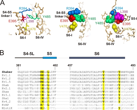
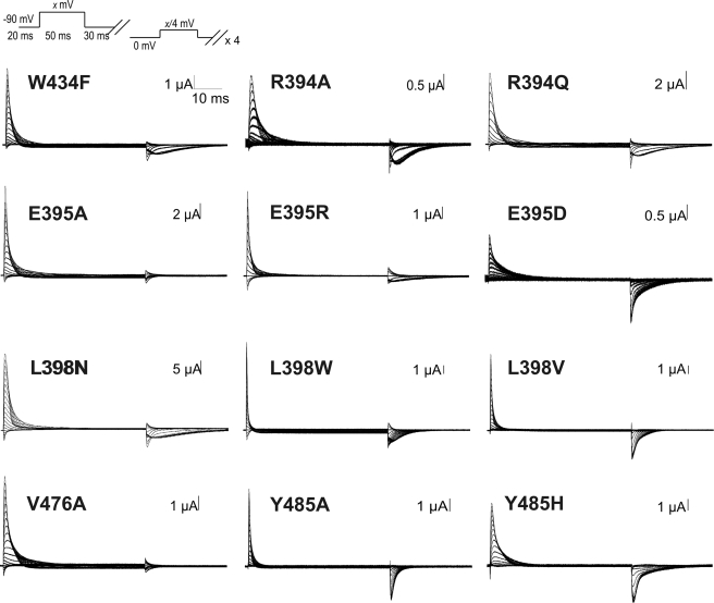
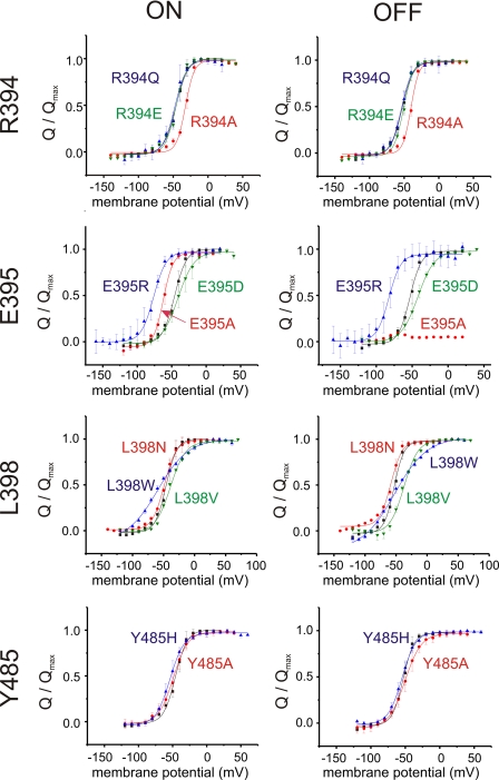
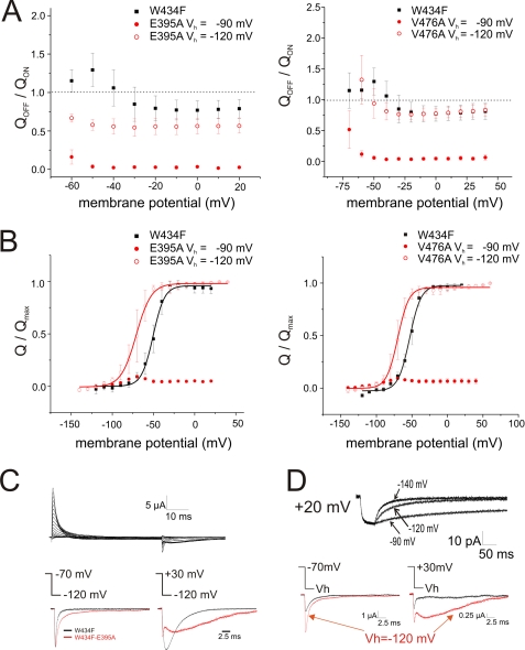
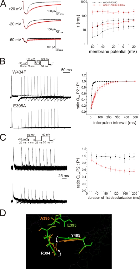
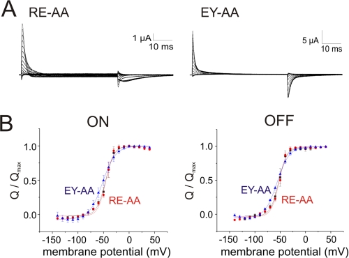
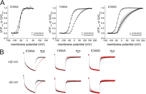
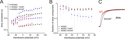
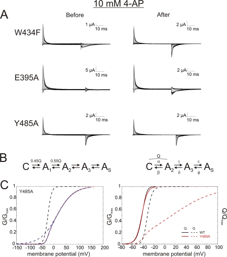
Voltage-gated ion channels are controlled by the membrane potential, which is sensed by peripheral, positively charged voltage sensors. The movement of the charged residues in the voltage sensor may be detected as gating currents. In Shaker K(+) channels, the gating currents are asymmetric; although the on-gating currents are fast, the off-gating currents contain a slow component. This slow component is caused by a stabilization of the activated state of the voltage sensor and has been suggested to be linked to ion permeation or C-type inactivation. The molecular determinants responsible for the stabilization, however, remain unknown. Here, we identified an interaction between Arg-394, Glu-395, and Leu-398 on the C termini of the S4-S5 linker and Tyr-485 on the S6 of the neighboring subunit, which is responsible for the development of the slow off-gating component. Mutation of residues involved in this intersubunit interaction modulated the strength of the associated interaction. Impairment of the interaction still led to pore opening but did not exhibit slow gating kinetics. Development of this interaction occurs under physiological ion conduction and is correlated with pore opening. We, thus, suggest that the above residues stabilize the channel in the open state.


Figures

FIGURE 1.
FIGURE 1.
Candidate interactions among residues on the S4-S5 linker and S6 of adjacent subunits in Shaker K+ channels. A, shown are side chains of the candidate amino acids (numbered as in Shaker) shown in stick (left) and space-filling (middle, right) representation in the Kv1.2 crystal structure (29). The S4-S5 linker and S6 of one subunit (I) and the S6 C terminus of the adjacent subunit (IV) are shown. The right-most image shows the same region as the other structures except it is rotated by ∼180°. B, alignment of sequences spanning the S4-S5 linker, N-terminal S5, and S6 of Drosophila (Shaker, Shab, Shaw, Shal), mammalian (Kv), and bacterial (KvAP, MLotiK) potassium channels. Using Shaker as a template, amino acids commonly conserved in the other channels are in bold, and residues involved in an S4-S5 linker/S6 interaction, shown in A, are highlighted in yellow.
FIGURE 2.
FIGURE 2.
Gating current profiles in Shaker mutants. Gating current traces representative of each mutation are shown after subtraction of capacitive currents using a P/4 protocol. Cut-open oocytes expressing W434F (control) or the various mutants were held at −90 mV, and depolarizations were made in 10-mV increments up to +60 to +100 mV.
FIGURE 3.
FIGURE 3.
Voltage dependence of gating charge (Q) in Shaker mutants. Shown are Boltzmann fits comparing normalized gating charge (Q) as a function of voltage in cut-open oocytes expressing W434F control (black) of the various mutants as labeled in the graphs. For E395A, the maximum off-gating charge was normalized to the average, normalized OFF-gating charge of W434F measured at the same depolarization.
FIGURE 4.
FIGURE 4.
Recovery of off-gating charge by reducing resting potential to −120 mV in E395A and V476A. A, shown is the QOFF/QON ratio as a function of voltage in E395A (left; n = 4) and V476A (right; n = 3). Black squares, W434F, Vh = −90 mV, n = 5; red filled circles, E395A/V476A Vh = −90 mV; red hollow circles, E395A/V476A Vh = −120 mV. Error bars show S.D. B, at a resting potential of −120 mV the voltage sensors are released from their immobilized state and allowed fitting of the data into a single Boltzmann curve. Off-gating charge and voltage relations between W434F (n = 5) and E395A (left; n = 4) and between W434F (n = 5) and V476A (right; n = 3), respectively. Black squares, W434F; red filled circles, E395A/V476A Vh = −90 mV; red empty circles, E395A/V476A Vh = −120 mV. Error bars show S.D. C, shown are representative gating traces elicited in the E395A mutant at a resting potential of Vh = −120 mV (top). Bottom, a comparison of off-gating between W434F (black) and W434F-E395A (red) is shown. D, the fluorescence trace compares voltage sensor movement after various repolarizations as shown after depolarization to +20 mV. Bottom, a comparison of off-gating currents for different holding potentials (black trace, Vh = −90 mV; red trace, Vh = −120 mV) is shown.
FIGURE 5.
FIGURE 5.
Charge immobilization of the voltage sensor in the E395A-W434F Shaker mutant. A, left, shown are voltage-clamp fluorometry results comparing W434F and E395A. Shown are representative fluorescent signals after depolarizations to +20, −20, and −60 mV (from Vh = −90 mV) for W434F (black traces) and E395A (red traces). Right, the time constants of the fluorescent decay curves during repolarization were plotted as a function of voltage (black, A359C/W434F; red, E395A/A359C/W434F, Vh = −90 mV, n = 5 or 6 for W434F and E395A, respectively; error bars show S.D.). B, left, shown are representative gating currents of cut-open oocytes expressing W434F or E395A after two sequential saturating depolarizations at +20 mV. The interpulse interval ranged from 1 to 301 ms in 25-ms steps. Capacitive currents were subtracted with P/4 protocol. Right, shown is a plot of the maximum amplitude of the on-gating current after the second depolarizing pulse (P2) normalized to the on-gating current after the first pulse (P1) as a function of the interpulse interval. Results were fit to an exponential curve with τ = 7 ms (W434F, black squares) and τ = 70 ms (E395A, red circles) (n = 5, error bars show S.D.). C, left, shown is a two-pulse protocol varying the duration of the first depolarizing pulse at −60 mV from 20 to 200 ms in 20-ms intervals. Capacitive currents were subtracted with P/4 protocol. Shown are gating currents produced in cut-open oocytes expressing W434F or E395A. Right, maximum amplitude after P2 normalized to that after P1 plotted as a function of the duration of P1 is shown. Average data were fit into an exponential decay function with one time constant. τ1 values were 235.7 and 61.4 ms for W434F (black squares) and E395A (red circles), respectively (n = 4, error bars show S.D.). D, S4-S6 regions of wild type and E327A mutant Kv1.2 (E395A in Shaker) were subjected to an energy minimization protocol. Molecular backbones of the minimized wild type (green) and E327A (orange) mutant structures were superimposed. Residue numbering is according to Shaker.
FIGURE 6.
FIGURE 6.
Gating current profiles in Shaker double mutants. A, gating current traces representative of RE-AA and EY-AA double mutants are shown after subtraction of capacitive currents using a P/4 protocol. Oocytes expressing W434F (control) or a double mutant were held at a resting potential of −90 mV and depolarizing pulses in 10-mV increments were applied. B, shown are Boltzmann fits of on- and off-gating currents in cut-open oocytes expressing RE-AA (red, n = 5) and EY-AA (blue, n = 5) versus W434F control (gray, n = 5). Error bars show S.D.
FIGURE 7.
FIGURE 7.
Electromechanical uncoupling of the voltage sensor and pore in Y485A and E395D mutants. A, shown are plots of conductance (ΔG/Gmax) and fluorescence (ΔF/Fmax) as a function of voltage in E395A/A359C, Y485A/A359C, and E395D/A359C mutants. Black-filled and open symbols represent normalized conductance and relative fluorescence change of the mutants E395A (conductance n = 8; fluorescence n = 4); Y485A (conductance n = 6; fluorescence n = 8); E395D (n = 6); error bars show S.D. B, voltage-clamp fluorometry results are shown comparing A359C with Y485A/A359C and E395D/A359C (right) and comparing M356C/T449Y with E395A/M356C-T449Y (left). Shown are representative fluorescent signals after depolarizations to +20 and −20 mV (from Vh = −90 mV) of mutant as shown (red traces) compared with their respective control (black traces).
FIGURE 8.
FIGURE 8.
Voltage sensor movement in the presence of permeating ions. A, time constants of double exponential fits to fluorescence decay after depolarizing pulses for ShakerIR-M356C (black), ShakerIR-M356C/T449Y (red), and ShakerIR-M356C/W434F (blue) are shown. B, shown is the fraction of the slower time constant in fluorescence traces analyzed in A. C, shown is a comparison of two fluorescence decays after a depolarizing pulse to +20 mV (red, Shaker-IR-M356C (wild type (WT)); black, Shaker-IR-M356C/W434F).
FIGURE 9.
FIGURE 9.
Slow OFF-gating components during voltage sensor deactivation are partially restored by 4-AP in the E395A mutant. A, shown are representative gating current traces in W434F control, E395A, and Y485A mutants before and after the addition of 10 mm 4-AP (W434F, n = 4; E395A, n = 3; Y485A, n = 5). B, 5-state model used to fit the data (left; see “Experimental Procedures”) and reduced model combining all charge carrying steps into the first transition (right) are shown. C, left, shown are GV and the double Boltzmann fit of ShakerIR-Y485A. The dashed lines visualize the two components of the double Boltzmann relation; right, modeling the effect of destabilization of the last transition on QV and GV is shown. The first two transitions of the reduced model were left unaltered, whereas the values from the fit (left, V½ = 14.8 mV, dV = 38 mV) were used for the last transition (red, Y485A; blue, wild type; solid line, QV; dashed line, GV; see “Discussion: for details).

Similar articles

Cited by

References

    1. Bezanilla F. (2008) Nat. Rev. Mol. Cell Biol. 9, 323–332 - PubMed
    1. Armstrong C. M., Bezanilla F., Rojas E. (1973) J. Gen. Physiol. 62, 375–391 - PMC - PubMed
    1. Bezanilla F., Armstrong C. M. (1974) Science 183, 753–754 - PubMed
    1. Hoshi T., Zagotta W. N., Aldrich R. W. (1990) Science 250, 533–538 - PubMed
    1. Zagotta W. N., Aldrich R. W. (1990) J. Gen. Physiol. 95, 29–60 - PMC - PubMed

Publication types

MeSH terms

Substances

LinkOut - more resources