Review
. 2010 Apr;7(4):513-33.
doi: 10.1517/17425241003628171.

Two-photon polymerization of microneedles for transdermal drug delivery

Affiliations
Review

Two-photon polymerization of microneedles for transdermal drug delivery

Shaun D Gittard et al. Expert Opin Drug Deliv. 2010 Apr.

Abstract

Importance of the field: Microneedles are small-scale devices that are finding use for transdermal delivery of protein-based pharmacologic agents and nucleic acid-based pharmacologic agents; however, microneedles prepared using conventional microelectronics-based technologies have several shortcomings, which have limited translation of these devices into widespread clinical use.

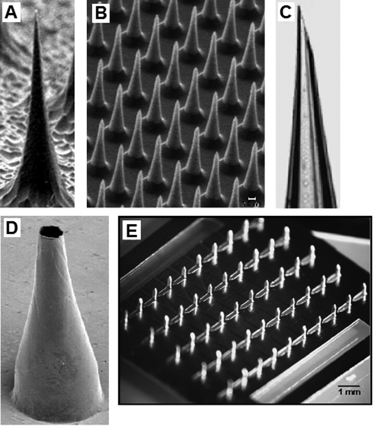
Areas covered in this review: Two-photon polymerization is a laser-based rapid prototyping technique that has been used recently for direct fabrication of hollow microneedles with a wide variety of geometries. In addition, an indirect rapid prototyping method that involves two-photon polymerization and polydimethyl siloxane micromolding has been used for fabrication of solid microneedles with exceptional mechanical properties.

What the reader will gain: In this review, the use of two-photon polymerization for fabricating in-plane and out-of-plane hollow microneedle arrays is described. The use of two-photon polymerization-micromolding for fabrication of solid microneedles is also reviewed. In addition, fabrication of microneedles with antimicrobial properties is discussed; antimicrobial microneedles may reduce the risk of infection associated with the formation of channels through the stratum corneum.

Take home message: It is anticipated that the use of two-photon polymerization as well as two-photon polymerization-micromolding for fabrication of microneedles and other microstructured drug delivery devices will increase over the coming years.


Conflict of interest statement

Declaration of interest

The authors state no conflicts of interest and have received no payment in the preparation of this manuscript.

Figures

Figure 1
Figure 1
(a) Solid silicon microneedle fabricated by reactive ion etching. (b) Solid silicon microneedle array fabricated by reactive ion etching. (c) Hollow glass microneedle fabricated using a micropipette puller. (d) Hollow metal microneedle fabricated by electroplating a master structure. (e) Solid metal microneedles fabricated by laser machining and bending a metal sheet. (a–d) Reprinted from the Proceedings of the National Academy of Sciences, Microfabricated needles for transdermal delivery of macromolecules and nanoparticles: Fabrication methods and transport studies, D. V. McAllister, P. M. Wang, S. P. Davis, J. H. Park, P. J. Canatella, M. G. Allen, M. R. Prausnitz, Vol 100, 13755–13760, Copyright (2003) National Academy of Sciences, U. S. A. (e) Reprinted from Journal of Controlled Release, Vol 117, H. S. Gill, M. R. Prausnitz, Coated microneedles for transdermal delivery, 227–237, Copyright (2007), with permission from Elsevier.
Figure 2
Figure 2
(a) Schematic of the two photon polymerization process. The energy distribution is a Gaussian shape. The radius of the polymerization voxel corresponds to the position at which the energy intensity exceeds the excitation threshold of the photoinitiator. (b) Single photon versus two photon polymerization. Single photon polymerization is limited to the surface of a given material. On the other hand, two photon polymerization may occur within a given material. (c) Schematic of the rapid prototyping process. In the first step, a computer-aided design program is used to prepare a STL format file. The STL format file is subsequently used to prepare a layer-by-layer contour of the structure. The structure is fabricated by rastering the laser in order to fill the area contained within the contours.
Figure 2
Figure 2
(a) Schematic of the two photon polymerization process. The energy distribution is a Gaussian shape. The radius of the polymerization voxel corresponds to the position at which the energy intensity exceeds the excitation threshold of the photoinitiator. (b) Single photon versus two photon polymerization. Single photon polymerization is limited to the surface of a given material. On the other hand, two photon polymerization may occur within a given material. (c) Schematic of the rapid prototyping process. In the first step, a computer-aided design program is used to prepare a STL format file. The STL format file is subsequently used to prepare a layer-by-layer contour of the structure. The structure is fabricated by rastering the laser in order to fill the area contained within the contours.
Figure 3
Figure 3
Scanning electron micrograph of microneedle array fabricated out of Ormocer® organically-modified ceramic material using two photon polymerization. Reprinted from American Ceramic Society Bulletin, Vol. 88, page 22, Copyright 2009, with permission from the American Ceramic Society.
Figure 4
Figure 4
Computer aided design diagrams of hollow Ormocer® microneedles with (a) 0 µm, (b) 1.4 µm, and (c) 20.4 µm needle center-pore displacement. Scanning electron micrographs of hollow Ormocer® microneedles with (a) 0 µm, (b) 1.4 µm, and (c) 20.4 µm needle center-pore displacement. Reprinted from International Journal of Applied Ceramic Technology, Vol. 4, Ovsianikov et al, Two photon polymerization of polymer–ceramic hybrid materials for transdermal drug delivery, 22–29, Copyright 2007, with permission from John Wiley & Sons Inc.
Figure 5
Figure 5
Scanning electron micrographs of microneedles with complex geometries. (a) Scanning electron micrograph of an Ormocer® rocket-shaped microneedle fabricated using two photon polymerization. The small cross-sectional area minimizes the skin penetration force. (b) Scanning electron micrograph of an Ormocer® mosquito geometry microneedle fabricated using two photon polymerization. The serrated tip provides stress concentrations, which decrease the skin penetration force. Image used with permission of the copyright owner (B. N. Chichkov).
Figure 5
Figure 5
Scanning electron micrographs of microneedles with complex geometries. (a) Scanning electron micrograph of an Ormocer® rocket-shaped microneedle fabricated using two photon polymerization. The small cross-sectional area minimizes the skin penetration force. (b) Scanning electron micrograph of an Ormocer® mosquito geometry microneedle fabricated using two photon polymerization. The serrated tip provides stress concentrations, which decrease the skin penetration force. Image used with permission of the copyright owner (B. N. Chichkov).
Figure 6
Figure 6
(a) DIC-fluorescence confocal microscopy images showing administration of fluorescein-conjugated biotin solution to porcine skin. The center columns and the right column demonstrate that administration of fluorescein-conjugated biotin solution to deeper layers of porcine skin was enabled by a microscale pore, which was created by an Ormocer® microneedle. The left column shows administration of fluorescein-conjugated biotin solution to porcine skin without microneedle enhancement. The topically administered fluorescein-conjugated biotin solution remained on the skin surface. Top row: DIC single-channel demonstrates stratum corneum (SC), deeper epidermis (E), and dermis (D) layers of the skin. Bottom row: DIC-fluorescence overlay (OVR) shows distribution of fluorescein-conjugated biotin solution within various skin layers. Scale bar equals 100 µm. (b) Scanning electron micrograph of polyethylene glycol 600 diacrylate miconeedles after exposure to platelet rich plasma. No protein aggregation and no platelet aggregation were observed on the polyethylene glycol 600 diacrylate microneedles. Small, widely scattered crystals were observed on the surface; the presence of sodium, chlorine, and phosphorus in energy dispersive X-ray spectroscopy data suggests that sodium chloride crystals precipitated from the platelet rich plasma.
Figure 6
Figure 6
(a) DIC-fluorescence confocal microscopy images showing administration of fluorescein-conjugated biotin solution to porcine skin. The center columns and the right column demonstrate that administration of fluorescein-conjugated biotin solution to deeper layers of porcine skin was enabled by a microscale pore, which was created by an Ormocer® microneedle. The left column shows administration of fluorescein-conjugated biotin solution to porcine skin without microneedle enhancement. The topically administered fluorescein-conjugated biotin solution remained on the skin surface. Top row: DIC single-channel demonstrates stratum corneum (SC), deeper epidermis (E), and dermis (D) layers of the skin. Bottom row: DIC-fluorescence overlay (OVR) shows distribution of fluorescein-conjugated biotin solution within various skin layers. Scale bar equals 100 µm. (b) Scanning electron micrograph of polyethylene glycol 600 diacrylate miconeedles after exposure to platelet rich plasma. No protein aggregation and no platelet aggregation were observed on the polyethylene glycol 600 diacrylate microneedles. Small, widely scattered crystals were observed on the surface; the presence of sodium, chlorine, and phosphorus in energy dispersive X-ray spectroscopy data suggests that sodium chloride crystals precipitated from the platelet rich plasma.

Similar articles

Cited by

References

    1. Khafagy ES, Morishita M, Onuki Y, Takayama K. Current challenges in non-invasive insulin delivery systems: A comparative review. Adv Drug Deliv Rev. 2007;59:1521–1546. - PubMed
    1. Brown MB, Martin GP, Jones SA, Akomeah FK. Dermal and transdermal drug delivery systems: Current and future prospects. Drug Deliv. 2006;13:175–187. - PubMed
    1. Prausnitz MR, Mitragotri S, Langer R. Current status and future potential of transdermal drug delivery. Nat Rev Drug Discov. 2004;3:115–124. - PubMed
    1. Chabri F, Bouris K, Jones T, et al. Microfabricated silicon microneedles for nonviral cutaneous gene delivery. Br J Dermatol. 2004;150:869–877. - PubMed
    1. Mukerjee EV, Collins SD, Isseroff RR, Smith RL. Microneedle array for transdermal biological fluid extraction and in situ analysis. Sensor Actuat A. 2004;114:267–275.

Publication types

MeSH terms

Substances