

DLP-based dichoptic vision test system
- PMID: 20210457
- PMCID: PMC2839799
- DOI: 10.1117/1.3292015
DLP-based dichoptic vision test system
Abstract
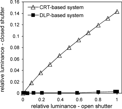
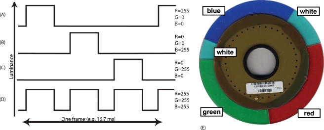
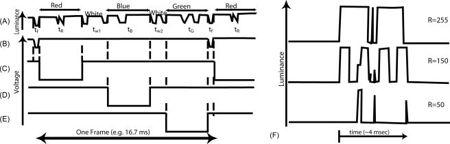
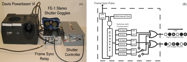
It can be useful to present a different image to each of the two eyes while they cooperatively view the world. Such dichoptic presentation can occur in investigations of stereoscopic and binocular vision (e.g., strabismus, amblyopia) and vision rehabilitation in clinical and research settings. Various techniques have been used to construct dichoptic displays. The most common and most flexible modern technique uses liquid-crystal (LC) shutters. When used in combination with cathode ray tube (CRT) displays, there is often leakage of light from the image intended for one eye into the view of the other eye. Such interocular crosstalk is 14% even in our state of the art CRT-based dichoptic system. While such crosstalk may have minimal impact on stereo movie or video game experiences, it can defeat clinical and research investigations. We use micromirror digital light processing (DLP) technology to create a novel dichoptic visual display system with substantially lower interocular crosstalk (0.3%; remaining crosstalk comes from the LC shutters). The DLP system normally uses a color wheel to display color images. Our approach is to disable the color wheel, synchronize the display directly to the computer's sync signal, allocate each of the three (former) color presentations to one or both eyes, and open and close the LC shutters in synchrony with those color events.
Figures
Similar articles
-
Measurement of crosstalk in stereoscopic display systems used for vision research.J Vis. 2016 Dec 1;16(15):14. doi: 10.1167/16.15.14. J Vis. 2016. PMID: 27978549 Free PMC article.
-
Dichoptic Attentive Motion Tracking is Biased Toward the Nonamblyopic Eye in Strabismic Amblyopia.Invest Ophthalmol Vis Sci. 2018 Sep 4;59(11):4572-4580. doi: 10.1167/iovs.18-25236. Invest Ophthalmol Vis Sci. 2018. PMID: 30242356
-
Interocular interactions during acuity measurement in children and adults, and in adults with amblyopia.Vision Res. 2007 Jan;47(2):179-88. doi: 10.1016/j.visres.2006.08.017. Epub 2006 Nov 28. Vision Res. 2007. PMID: 17126872
-
Review of dichoptic color mixing.Optom Vis Sci. 1989 Mar;66(3):181-90. doi: 10.1097/00006324-198903000-00010. Optom Vis Sci. 1989. PMID: 2654794 Review.
-
Psychophysics of suppression.Eye (Lond). 1996;10 ( Pt 2):270-3. doi: 10.1038/eye.1996.57. Eye (Lond). 1996. PMID: 8776459 Review.
Cited by
-
Reorganization of visual processing in age-related macular degeneration depends on foveal loss.Optom Vis Sci. 2014 Aug;91(8):e199-206. doi: 10.1097/OPX.0000000000000325. Optom Vis Sci. 2014. PMID: 24978868 Free PMC article.
-
Tunnel Vision Prismatic Field Expansion: Challenges and Requirements.Transl Vis Sci Technol. 2015 Dec 31;4(6):8. doi: 10.1167/tvst.4.6.8. eCollection 2015 Dec. Transl Vis Sci Technol. 2015. PMID: 26740910 Free PMC article.
-
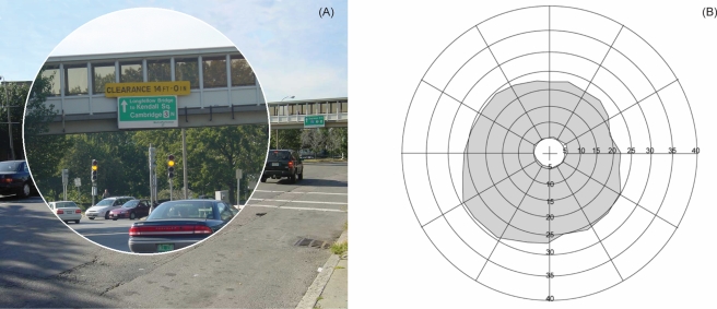
Torsional anomalous retinal correspondence effectively expands the visual field in hemianopia.Optom Vis Sci. 2012 Sep;89(9):E1353-63. doi: 10.1097/OPX.0b013e3182678d42. Optom Vis Sci. 2012. PMID: 22885782 Free PMC article.
-
Measurement of crosstalk in stereoscopic display systems used for vision research.J Vis. 2016 Dec 1;16(15):14. doi: 10.1167/16.15.14. J Vis. 2016. PMID: 27978549 Free PMC article.
-
Object detection in the ring scotoma of a monocular bioptic telescope.Arch Ophthalmol. 2011 May;129(5):611-7. doi: 10.1001/archophthalmol.2011.85. Arch Ophthalmol. 2011. PMID: 21555615 Free PMC article.
References
-
- Howard I. P. and Rogers B. J., Binocular Vision and Stereopsis, Oxford University Press, Oxford, UK: (1995).
-
- Sheedy J. E., “Actual measurement of fixation disparity and its use in diagnosis and treatment,” J. Am. Optom. Assoc. JOAPBD 51(12), 1079–1084 (1980). - PubMed
-
- Sheedy J. E. and Saladin J. J., “Validity of diagnostic criteria and case analysis in binocular vision disorders,” in Vergence Eye Movements: Basic and Clinical Aspects, Schor C. M. and Ciuffreda K. J., Eds., Butterworths, Boston: (1983).
-
- Waltuck M., McKnight R., and Peli E., “Visual function tester with binocular vision testing,” US patent no. 5,026,151, Mentor O & O, Norwell, MA (1997).
MeSH terms
Grants and funding
LinkOut - more resources
Full Text Sources
Other Literature Sources
Research Materials
