

doi: 10.1039/b917743d.
Epub 2010 Jan 5.
Surface-patterned electrode bioreactor for electrical stimulation
Affiliations
- PMID: 20221556
- PMCID: PMC3618471
- DOI: 10.1039/b917743d
Item in Clipboard
Surface-patterned electrode bioreactor for electrical stimulation
Lab Chip.
.
Abstract
We present a microscale cell culture system with an interdigitated microarray of excimer-laser-ablated indium tin oxide electrodes for electrical stimulation of cultured cells. The system has been characterized in a range of geometeries and stimulation regimes via electrochemical impedance spectroscopy and used to culture primary cardiomyocytes and human adipose derived stem cells. Over 6 days of culture with electrical stimulation (2 ms duration, 1 Hz, 180 microm wide electrodes with 200 microm spacing), both cell types exhibited enhanced proliferation, elongation and alignment, and adipose derived stem cells exhibited higher numbers of Connexin-43-composed gap junctions.
Figures
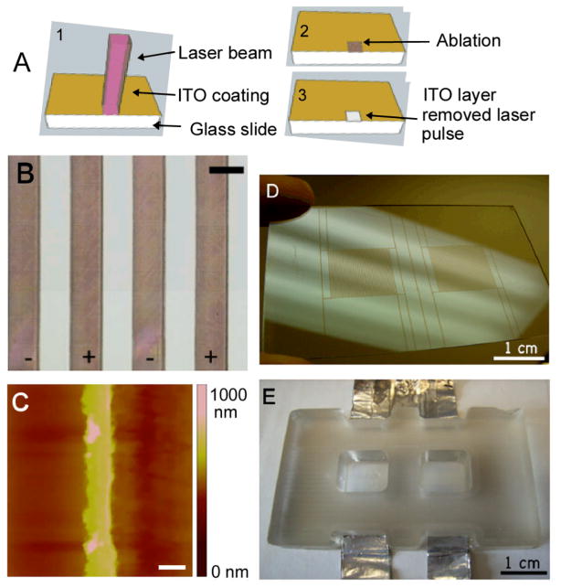
(A) Schematic of the laser-ablation process of the indium-tin-oxide substrates. (B) Closeup image of patterned electrode array with 200 μm electrodes and 200 μm spacing (scale bar corresponds to 200 μm). (C) Atomic force micrograph of a 50 μm-wide electrode patterned via laser ablation (scale bar: 50 μm) (D) Photograph of slide patterned with two interdigitated electrode arrays. (E) Photograph of bioreactor with two culture wells (employed for all studies reported here).
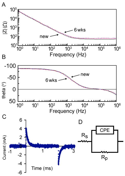
(A–B) Bode plot of (A) electrode impedance and (B) phase versus frequency for a new (solid) and aged (dotted) ITO electrode array (used for 6 weeks of continuous stimulation) with 180 μm electrodes and 200 μm spacing. (C) Graph of current for ITO electrode array with 180 μm electrodes and 200 μm spacing and input stimulus of 250 mV. (D) Equivalent circuit for modeling the electrochemical behavior of the ITO electrode array.
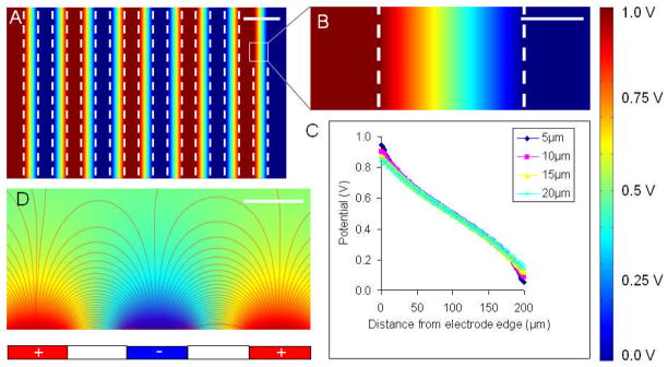
(A,B,D) A colormap of electric potential and (C) potential vs. position plot are shown for an ITO electrode array with 200 μm electrodes and 200 μm spacing with an applied voltage of 1 V. (A) top view of five pairs of positive and negative electrodes. (B) close-up of the space between a single positive and negative electrode (dashed lines indicate electrode edges). (C) plot of potential vs. position at different heights above the glass surface between the electrodes. (D) cross-sectional view of the electrical field lines between electrodes. Scale bars: (A) 300 μm, (B) 100 μm, (D) 200 μm.
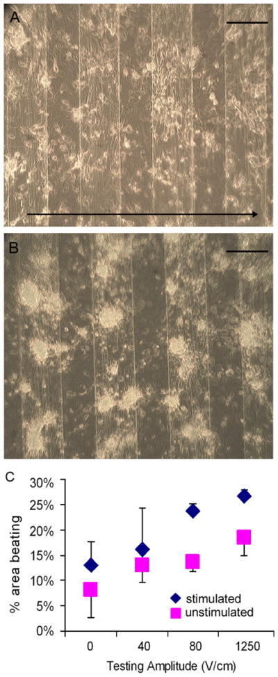
Bright field images of cells at day 4 of culture either with (A) or without (B) electrical stimulation. Arrow in section A shows the direction of the applied electric field. Graph (C) represents the percent area beating per well for cardiac cells cultured with (blue) or without (pink) electrical stimulation for a range of testing stimuli. Scale bar corresponds to 200 μm.

(A,B) F-Actin (red) and DAPI (blue) of ASC culture with (A) or without (B) electrical stimulation. (C,D) Connexin-43 (green) and DAPI (blue) of ASC culture with (C) or without (D) electrical stimulation. Arrows in sections A and C show the direction of the applied electric field. Graphs (E, F, G) show (E) the number of measured gap junctions per cell, (F) the number of cells measured per mm2 and (G) the direction of actin fibers for ASCs cultured with (+ES) or without (−ES) electrical stimulation. *represents statistically significant difference (p<0.01). Scale bar corresponds to 100 μm.
Similar articles
-
Characterization of electrical stimulation electrodes for cardiac tissue engineering.Conf Proc IEEE Eng Med Biol Soc. 2006;2006:845-8. doi: 10.1109/IEMBS.2006.259747. Conf Proc IEEE Eng Med Biol Soc. 2006. PMID: 17946862
-
An electro-tensile bioreactor for 3-D culturing of cardiomyocytes. A bioreactor system that simulates the myocardium's electrical and mechanical response in vivo.IEEE Eng Med Biol Mag. 2005 Jul-Aug;24(4):73-9. doi: 10.1109/memb.2005.1463399. IEEE Eng Med Biol Mag. 2005. PMID: 16119216 No abstract available.
-
Design and validation of a bioreactor for simulating the cardiac niche: a system incorporating cyclic stretch, electrical stimulation, and constant perfusion.Tissue Eng Part A. 2013 Feb;19(3-4):403-14. doi: 10.1089/ten.TEA.2012.0135. Epub 2012 Dec 10. Tissue Eng Part A. 2013. PMID: 22991978
-
Electrical and mechanical stimulation of cardiac cells and tissue constructs.Adv Drug Deliv Rev. 2016 Jan 15;96:135-55. doi: 10.1016/j.addr.2015.07.009. Epub 2015 Jul 30. Adv Drug Deliv Rev. 2016. PMID: 26232525 Free PMC article. Review.
-
Tissue engineering bioreactor systems for applying physical and electrical stimulations to cells.J Biomed Mater Res B Appl Biomater. 2015 May;103(4):935-48. doi: 10.1002/jbm.b.33268. Epub 2014 Aug 29. J Biomed Mater Res B Appl Biomater. 2015. PMID: 25171208 Review.
Cited by
-
Tailoring cardiac environment in microphysiological systems: an outlook on current and perspective heart-on-chip platforms.Future Sci OA. 2017 May 3;3(2):FSO191. doi: 10.4155/fsoa-2017-0024. eCollection 2017 Jun. Future Sci OA. 2017. PMID: 28670478 Free PMC article. No abstract available.
-
Contact photolithography-free integration of patterned and semi-transparent indium tin oxide stimulation electrodes into polydimethylsiloxane-based heart-on-a-chip devices for streamlining physiological recordings.Lab Chip. 2021 Feb 23;21(4):674-687. doi: 10.1039/d0lc00948b. Lab Chip. 2021. PMID: 33439202 Free PMC article.
-
Architecture design and advanced manufacturing of heart-on-a-chip: scaffolds, stimulation and sensors.Microsyst Nanoeng. 2024 Jul 11;10:96. doi: 10.1038/s41378-024-00692-7. eCollection 2024. Microsyst Nanoeng. 2024. PMID: 39006908 Free PMC article. Review.
-
Recent Advances in Cardiac Tissue Engineering for the Management of Myocardium Infarction.Cells. 2021 Sep 25;10(10):2538. doi: 10.3390/cells10102538. Cells. 2021. PMID: 34685518 Free PMC article. Review.
-
Biomimetic platforms for human stem cell research.Cell Stem Cell. 2011 Mar 4;8(3):252-61. doi: 10.1016/j.stem.2011.02.014. Cell Stem Cell. 2011. PMID: 21362565 Free PMC article.
References
Publication types
MeSH terms
Grants and funding
LinkOut - more resources
Full Text Sources
Other Literature Sources
Miscellaneous