. 2010 Mar 11;65(5):706-17.
doi: 10.1016/j.neuron.2010.02.021.

Preceding inhibition silences layer 6 neurons in auditory cortex

Affiliations

Preceding inhibition silences layer 6 neurons in auditory cortex

Yi Zhou et al. Neuron. .

Abstract

A canonical feedforward circuit is proposed to underlie sensory cortical responses with balanced excitation and inhibition in layer 4 (L4). However, in another input layer, L6, sensory responses and the underlying synaptic circuits remain largely unclear. Here, cell-attached recordings in rat primary auditory cortex revealed that for the majority of L6 excitatory neurons, tonal stimuli did not drive spike responses, but suppressed spontaneous firings. Whole-cell recordings further revealed that the silencing resulted from tone-evoked strong inhibition arriving earlier than excitation. This pattern of inputs can be attributed to a parallel feedforward circuit with both excitatory and inhibitory inputs disynaptically relayed. In contrast, in the other neurons directly driven by thalamic input, stimuli evoked excitation preceding relatively weak inhibition, resulting in robust spike responses. Thus, the dichotomy of L6 response properties arises from two distinct patterns of excitatory-inhibitory interplay. The parallel circuit module generating preceding inhibition may provide a gating mechanism for conditional corticothalamic feedback.


Figures

Figure 1
Figure 1
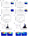
Spike TRFs of individual neurons in layer 6 of the rat A1. (A) An example normal-type (N-type) neuron as determined by cell-attached recording. Left, spike TRF mapped in one trial. Each small trace (100 ms) in the frequency-intensity space represents the response of the cell to a tone of a particular frequency and intensity. Right, the color map displays the cell's spike TRF with the color representing the average firing rate. Twenty randomly selected individual spikes are superimposed below the color map. The cell is a typical regular-spike (RS) neuron according to the spike shape. (B) An example silent-type (S-type) neuron. Data are presented in the similar manner as in (A). TRF of local field potential (LFP) at recording site is displayed below the corresponding spike TRF. Note that both N- and S-type neurons are only defined for regular-spike pyramidal neurons. (C) An example fast-spike (FS) interneuron. Note that the interval between the negative and positive peaks of the spike shape is shorter than that of regular-spike neurons. (D) Upper panel, average bandwidth (responding frequency range) of spike TRFs for different types of neurons in layer 4 and 6. Bandwidth was measured at 30 dB above the threshold intensity of the TRF (BW30). The numbers of cells are indicated. RS(N): regular-spike normal-type neuron. Bar represents SEM. *, p < 0.1; **, p<0.002, ANOVA and post hoc Scheffe test. Lower panel, average rate of spontaneous and tone-evoked spikes (after subtraction of the basal level activity) of all the recorded RS neurons in layer 6. The evoked firing rate was averaged from responses at the characteristic frequency (CF) at from 20 dB above intensity threshold to 70 dB SPL. The CF was determined by the TRF of local field potentials in the case of silent-type neurons. Cells recorded under different anaesthesia are indicated. R and L indicate that recordings were made in the right and left hemisphere, respectively. Tone stimuli were always applied to the contralateral ear. Clustering (N- and S- type) is based on K-means method.
Figure 2
Figure 2
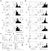
Membrane potential TRFs of the two types of excitatory neurons in layer 6. (A) An example silent-type neuron. Upper left, spike TRF mapped in one trial. Each small trace is a 100 ms response trace under current-clamp mode. Upper right, color map displays the spike TRF with the color representing the average firing rate. An example spike is shown below. Lower panel, membrane potential responses with the spikes removed (using a 10 ms median filter). Color represents the average peak amplitude of the evoked membrane potential change. Three enlarged response traces are shown. (B) An example normal-type neuron. Data are presented in the same manner as in (A). (C) The peak amplitude of evoked membrane potential change versus the response onset latency. Each data point represents one cell. Response to tone at the best frequency at 70 dB was measured. Clustering is based on K-means method. Triangle is the clustering center and whiskers are the corresponding standard deviation from the center.
Figure 3
Figure 3
Excitatory and inhibitory synaptic TRFs of example layer 6 neurons. (A) A putative normal-type neuron (cell #1). Left, small traces are excitatory and inhibitory synaptic currents recorded under -80 mV (upper) and 0 mV (lower) respectively, in response to tones of various frequencies and intensities. Right, color represents the peak amplitude of the evoked synaptic current. (B) The peak amplitude of inhibitory conductance versus that of the excitatory conductance activated by the same tone stimulus, plotted for cell #1. Data are from the responses to 70 dB tones at various effective frequencies. Dash line is the unity line. r, correlation coefficient; p, correlation significance. (C) Left, top, average excitatory (red) and inhibitory (blue) currents of cell #1 in response to the tone at 70 dB and the best frequency. Scale: 50 pA and 50 ms. Bottom, comparison of the rising phases of the two synaptic responses (30ms trace). The excitatory response is reversed in polarity and normalized in amplitude. Two dotted lines indicate the onset timings. Right, distribution of relative latency (i.e. the difference between the onset latencies of excitatory and inhibitory responses, Δt = TE – TI) for cell #1's responses to 70 dB tones at various effective frequencies. (D) TRF of membrane potential responses derived from excitatory input only (left) and by integrating excitatory and inhibitory inputs (right) for the cell #1. Color represents the peak amplitude of the membrane potential response. The resting membrane potential of the cell was -65 mV, and 20 mV above the resting potential was set as the spike threshold. The estimated spike response region is outlined by the dashed curve. (E-H) A putative silent-type neuron (cell #6). Data are presented in the same manner as in (A-D). Scale: 50 pA and 50 ms in (G).
Figure 4
Figure 4
Synaptic TRF properties of normal- and silent-type neurons in layer 6. (A) Four other putative normal-type neurons (cell numbers are indicated on the left). Left, the peak amplitude of inhibitory conductance versus that of the excitatory conductance activated by the same stimulus for effective tones at 70 dB. Right, distribution of relative latency of for the same set of responses. Inset, example excitatory (red) and inhibitory (blue) responses. Each trace is an average of three responses to 70 dB tones at or near the best frequency. (B) Six other putative silent-type neurons. Data are presented in the same manner as in (A). (C) Average peak amplitudes of excitatory (Ex) and inhibitory (In) conductances evoked by three 70 dB tones at and near the best frequency. Data points for the same cell are connected by a line. **, p <0.01, paired t-test. (D) Average onset latencies of excitatory and inhibitory conductances as in (C). **, p <0.01, paired t-test. (E) The relative latency versus the ratio between the peak amplitudes of evoked inhibitory and excitatory conductances (I/E ratio), based on the data shown in (C) and (D). Clustering is based on K-means method. (F) The percentage reduction of the total frequency responding range of spike responses after integration of inhibition. Comparison was made between spike responses to 70 dB tones derived from excitation alone and by integrating both excitation and inhibition.
Figure 5
Figure 5
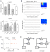
Modeling the impacts of excitatory and inhibitory inputs on membrane potential responses. (A) Left, temporal profiles of the evoked excitatory (red) and inhibitory (blue) conductances used in the model (see Experimental Procedures). The peak conductances are 2 nS (red)/1 nS (blue) for an average normal-type neuron and 2 nS (red)/6 nS (blue) for a silent-type neuron. Scale: 1 nS and 5 ms. Right, temporal profiles of the membrane potential responses (Vm) derived by integrating the excitatory and inhibitory inputs. Scale: 3mV (upper)/1mV (bottom),10 ms. (B) The peak amplitude of the evoked membrane depolarizing response versus the relative level of inhibition. Vm represents the peak amplitude of the depolarization in the simulated membrane potential response. The peak excitatory conductance was set at 2 nS, and the relative latency was set at 2 ms. Two dashed lines mark the level of the resting membrane potential (Vr) and the spike threshold (Vth). Responses below the Vr are omitted. (C) The level of membrane depolarizing response versus the strength of the excitatory input. The I/E ratio was set at 3, and the relative latency was set at 2 ms. (D) The level of membrane depolarizing response versus the relative latency. The strengths of excitatory and inhibitory inputs were fixed at 2 and 6 nS respectively.
Figure 6
Figure 6
Onset latencies of spike and synaptic responses of layer 4 and layer 6 neurons. (A) Top, average onset latencies of spike responses (shaded bars) of layer 4 RS excitatory neurons and FS inhibitory neurons, as well as of the excitatory (grey bar) and inhibitory responses (white bar) of excitatory neurons. Bar = SEM. **, p<0.01, t-test. ***, p<0.001, paired t-test. Bottom, onset latencies for layer 6 neurons, presented in a similar manner as in (A). *, p<0.05, t-test. **, p<0.01, paired t-test. “N”, “S” and “FS” refer to the normal-type excitatory, silent-type excitatory and fast-spike inhibitory neurons respectively. (B) Excitatory TRFs of two example layer 6 neurons recorded in the silenced cortex. (C) Distribution of onset latencies of the membrane potential response (Vm) and excitatory response in the control cortex (Exc), as well as the excitatory response in the silenced cortex (Exs). Putative normal-type and silent-type neurons are represented by cross and triangle marks respectively. (D) Left, schematic drawing of canonical feedforward circuit for recorded layer 4 neurons and layer 6 normal-type neurons (recording electrode is drawn in grey). TH, thalamus. Triangle, excitatory neurons. Circle, FS inhibitory neurons. Arrow head, excitatory connection. Bar, inhibitory connection. Right, proposed parallel feedforward circuit for recorded layer 6 silent-type neurons. At least some of these neurons project back to the thalamus.

Similar articles

Cited by

References

    1. Anderson JS, Carandini M, Ferster D. Orientation tuning of input conductance, excitation, and inhibition in cat primary visual cortex. J Neurophysiol. 2000;84:909–926. - PubMed
    1. Atencio CA, Schreiner CE. Spectrotemporal processing differences between auditory cortical fast-spiking and regular-spiking neurons. J Neurosci. 2008;28:3897–3910. - PMC - PubMed
    1. Borg-Graham LJ, Monier C, Frégnac Y. Visual input evokes transient and strong shunting inhibition in visual cortical neurons. Nature. 1998;393:369–373. - PubMed
    1. Crick F. Function of the thalamic reticular complex: the search-light hypothesis. Proc Natl Acad Sci USA. 1984;81:4586–4590. - PMC - PubMed
    1. Crick F, Koch C. Constraints on cortical and thalamic projections: the no-strong-loops hypothesis. Nature. 1998;391:245–250. - PubMed

Publication types

MeSH terms

LinkOut - more resources