Review
. 2010 Apr 20;49(15):3216-24.
doi: 10.1021/bi902202q.

Logic-based models for the analysis of cell signaling networks

Affiliations
Free PMC article
Review

Logic-based models for the analysis of cell signaling networks

Melody K Morris et al. Biochemistry. .
Free PMC article

Abstract

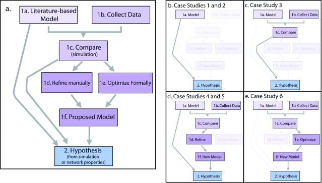
Computational models are increasingly used to analyze the operation of complex biochemical networks, including those involved in cell signaling networks. Here we review recent advances in applying logic-based modeling to mammalian cell biology. Logic-based models represent biomolecular networks in a simple and intuitive manner without describing the detailed biochemistry of each interaction. A brief description of several logic-based modeling methods is followed by six case studies that demonstrate biological questions recently addressed using logic-based models and point to potential advances in model formalisms and training procedures that promise to enhance the utility of logic-based methods for studying the relationship between environmental inputs and phenotypic or signaling state outputs of complex signaling networks.


Figures

Figure 1
Figure 1
Examples of a logic-based network. (a) Protein signaling network. Biochemical species are represented as nodes. The interactions between these nodes are indicated with arrows. (b) Logic gate. Precisely how the nodes interact is specified with a simple Boolean logic gate. (c) Truth table specifying the output node given possible combinations of its inputs nodes’ values. (d) Boolean logic gates and their truth tables. If the gates are used in the example network, the interaction is shown on the right. We also describe the AND-NOT gate, which is used in the example network. We note that, in many applications of logic-based modeling, OR and AND gates are not explicitly indicated with their gate symbols. (e) Example of a logic-based network structure. The model was simulated with synchronous updating using custom MatLab (Mathworks, Inc.) code (available as Supporting Information). (f) Network behavior with binary rules. Under initial conditions with different ligand stimulations, the network response was identical because the logic rules did not distinguish between EGF and HRG stimulation. (g) Multistate rule specification. The truth tables are given for each modeled species. These rules specify multiple states. The greater sensitivity of EGFR for EGF than HRG is encoded in the higher level it reaches upon stimulation by EGF. Rules that are different from the binary rules are highlighted. (h) Network behavior with multistate rules given in panel d. The rules specified that EGFR is more sensitive to EGF than HRG. Thus, the behavior differed depending on the stimulation condition. Under EGF or EGF and HRG stimulation, the states of ERK and AKT were stabilized whereas they oscillated under HRG stimulation alone. This is because the rules specified that, with the highest level of activation of EGFR (activation state two), the negative feedback by ERK did not effectively inhibit PI3K, whereas with medium-level activation of EGFR (activation state one accessed with only HRG was present), the negative feedback was effective.
Figure 2
Figure 2
Description of logic-based formalisms. (a) Description of various forms of logic-based models. All logic-based models describe species’ interactions in terms of logical statements (or rules). Discrete logic can specify two or more levels for each modeled species, whereas Boolean logic specifies only two levels of each species. In addition to these logic-based formalisms, various methods of describing discrete or Boolean logic models with piece-wise continuous equations (37) or logic-based ODEs (28) have been successfully implemented to represent biochemical signaling networks. (b) Approximation of the input−output relationship between hypothetical biological species (black solid line) with binary (red solid line), ternary (green dashed line), and quaternary (blue dashed−dotted line) discrete logic gates as well as fuzzy logic or mixed discrete-continuous formalisms (orange dashed line). Various thresholds could be chosen for each discrete gate; chosen thresholds are purely hypothetical. (c) Plane of granularity in species’ states and treatment of time. Regions containing various logic-based modeling variants are denoted by shaded boxes. Boolean networks (blue region) are binary, but their treatment of time ranges from logic steady state to discrete with delays. Discrete models with multiple species states (orange region) cover a similar range of possible treatments of time. Fuzzy logic models (green region) describe a continuous range of species’ states with the same range of time granularity. Conversion of Boolean or discrete models into logic-based ODEs, piecewise linear, and standardized qualitative dynamical system (purple region) results in models that are continuous in both species’ states and time. Each case study is placed on the landscape according to how it represents the biological system of interest with a logic-based network.
Figure 3
Figure 3
Workflow of application of logic-based models to answer biological questions. (a) General workflow. The workflow is divided into two phases: an initial model building phase (purple boxes) and a model prediction phase (blue box). Hypotheses are made from models built either from literature (box 1a) or from a comparison of a literature-based model with data (boxes 1a−c). In some cases, the models are refined manually (box 1d) or optimized formally (box 1f) with data and then used to make hypotheses (boxes 1a−f). (b) Workflow of case studies 1 and 2. These case studies analyze network properties of logic-based models built from the literature and use them to make experimentally testable predictions. (c) Workflow of case study 3. This case study compares the results of experiments to simulation results of a logic-based network to make predictions. They also analyze the network properties of their logic-based network. (d) Workflow of case studies 4 and 5. Both case studies manually refine their models based on experimental data, and prior to refinement, case study 5 first uses a model built from the literature to predict experimental outcome. (e) Workflow of case study 6. This case study compares logic-based models to experimental data and presents a formal method of training a Boolean network model to data.

Similar articles

Cited by

References

    1. Kestler H. A.; Wawra C.; Kracher B.; Kuhl M. (2008) Network modeling of signal transduction: Establishing the global view. BioEssays 30, 1110–1125. - PubMed
    1. Heinrichs A., Kritikou E., Pulverer B., and Raftopoulou M., Eds. (2006) Systems biology: A user's guide, Nature Publishing Group, New York.
    1. Janes K. A.; Lauffenburger D. A. (2006) A biological approach to computational models of proteomic networks. Curr. Opin. Chem. Biol. 10, 73–80. - PubMed
    1. Ideker T.; Lauffenburger D. (2003) Building with a scaffold: Emerging strategies for high- to low-level cellular modeling. Trends Biotechnol. 21, 255–262. - PubMed
    1. Aldridge B. B.; Burke J. M.; Lauffenburger D. A.; Sorger P. K. (2006) Physicochemical modelling of cell signalling pathways. Nat. Cell Biol. 8, 1195–1203. - PubMed

Publication types