Review
. 2011 Jan;32(1):3-13.
doi: 10.3174/ajnr.A2041. Epub 2010 Mar 18.

Principles and limitations of computational algorithms in clinical diffusion tensor MR tractography

Affiliations
Review

Principles and limitations of computational algorithms in clinical diffusion tensor MR tractography

H-W Chung et al. AJNR Am J Neuroradiol. 2011 Jan.

Abstract

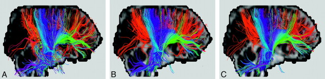
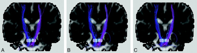
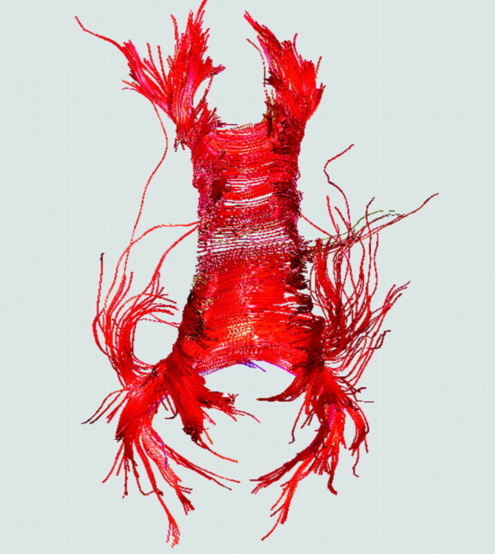
There have been numerous reports documenting the graphic reconstruction of 3D white matter architecture in the human brain by means of diffusion tensor MR tractography. Different from other reviews addressing the physics and clinical applications of DTI, this article reviews the computational principles of tractography algorithms appearing in the literature. The simplest voxel-based method and 2 widely used subvoxel approaches are illustrated first, together with brief notes on parameter selection and the restrictions arising from the distinct attributes of tract estimations. Subsequently, some advanced techniques attempting to offer improvement in various aspects are briefly introduced, including the increasingly popular research tracking tool using HARDI. The article explains the inherent technical limitations in most of the algorithms reported to date and concludes by providing a reference guideline for formulating routine applications of this important tool to clinical neuroradiology in an objective and reproducible manner.


Figures

Fig 1.
Fig 1.
Colored white matter tracts rendered for a patient with a falx meningioma (yellow) on the right hemisphere near the location of the precentral primary motor cortex, superimposed on a coronal T2-weighted image. Blue is used for the corticospinal tracts, for which the right-sided fiber bundles are displaced by the presence of the meningioma. Note that though differential diagnosis for meningioma is relatively straightforward using conventional T1- and T2-weighted MR imaging, hence making diffusion MR tractography unnecessary, the example shown here at least demonstrates the validity of the displaced tracts reconstructed from DTI data.
Fig 2.
Fig 2.
A, Schematic drawing showing the relationship between the diffusion tensor ellipsoid and the underlying white matter fiber bundle. The direction of the longest axis of the ellipsoid, mathematically called the principal eigenvector of the diffusion tensor (e1), corresponds to the major fiber direction where water molecules exhibit the fastest diffusion due to lack of a barrier. This direction is the most important information used in all tractography algorithms, whereas the other 2 axes (e2 and e3) of the diffusion tensor ellipsoid are used in only some of the methods. B, The diffusion tensor ellipsoid can be obtained on a voxel-by-voxel basis. The color-coding scheme is shown on the lower left corner.
Fig 3.
Fig 3.
A, Connection of fiber tracts at the voxel level can be achieved by examining the directional consistency of 2 relationships: one between the principal eigenvectors (thick black arrows, angle δ) of the 2 voxels under examination for connectivity (shaded) and the other between the fiber direction and the vector connecting the 2 voxels (thick gray arrow, angle θ). If either of the 2 angles is larger than a prespecified threshold (eg, 18°), as shown on the left, these 2 voxels are not considered connected. When both of these angles are smaller than the threshold, connections are formed as on the right. The examination process then proceeds to the next voxel to continue the tracking. B, Schematic drawing illustrating a popular subvoxel tractography algorithm on a region consisting of 4 × 4 voxels. With seed points chosen in certain voxels (shaded), the tracts simply follow the direction of the principal eigenvector until reaching the voxel boundary, after which the tracts enter a neighboring voxel to continue the tracking process. Note that different seed points, even if placed in the same starting voxel, could lead to distinct tracking results as shown in this example. C, The computed tracts in subvoxel tractography can be made smoother by using smaller steps (one-tenth of the voxel width in this example) during the fiber tracking process. Successive alteration of the tract direction is performed (short black arrows) by using distance-weighted interpolation of the 2 principal eigenvectors (long gray arrows) of the diffusion tensor ellipsoids in the 2 neighboring voxels.
Fig 4.
Fig 4.
Bilateral corticospinal tracts of a healthy subject with the 2 white regions on the coronal views selected to place the seed points. The obvious spurious tracts shown in A can be removed by selecting one more region of interest (the translucent box in B) to filter out unwanted tracts that do not pass through this region. This procedure is called tract editing and can be used in virtually all tractography algorithms. For this example, fiber assignment by continuous tracking is used.
Fig 5.
Fig 5.
A, Fiber crossing within 1 image voxel can be resolved by using HARDI, where the directions of the multiple fiber bundles are depicted by orientation distribution functions magnified in the lower right corner. In the example acquired by using 1 HARDI acquisition method called Q-ball imaging as shown here, the shape of the colored orientation distribution functions shows 2 intersecting elongated objects, representing the presence of 2 major fiber tracts in the anterior body of the corpus callosum and the cingulum. B, With the orientation distribution functions obtained for all image voxels from high angular resolution diffusion imaging, fiber tracts can be connected with many possibilities. Schematic tract examples (colored thick line segments) representing 2 fiber bundles in the anterior body of the corpus callosum and the cingulum as shown in A cross each other at an oblique angle.
Fig 6.
Fig 6.
Tractography results obtained from a healthy subject, showing tracts possibly associated with the seed point placed at the lower level of the internal capsule with connection probability >0.1 (A) and 0.01 (B), respectively. Note that it is generally believed that the corticospinal tracts do not cross to the contralateral hemisphere through the corpus callosum, indicating that users have to be cautious when selecting the probability threshold to display the results. In this case, therefore, a probability threshold of 0.1 seems to be a preferred choice to 0.01. The example shown here was processed with Bayesian probabilistic tractography with 30 diffusion-encoding directions acquired.
Fig 7.
Fig 7.
A, Errors in the estimation of fiber orientation can be graphically depicted on a voxel-by-voxel basis by using, for example, the double-cone diagram, in which the principal eigenvector of a diffusion tensor ellipsoid in an image voxel (upper right) is now replaced by a double cone (lower left), whose angular width represents the data-fitting uncertainty. B, An example of the double-cone map showing the fiber direction and its uncertainty simultaneously, overlaid on the original gray-scale transaxial FA map. From the magnified region (covering part of the corpus callosum and the corona radiata), it is seen that voxels showing high FA values such as the callosal fibers tend to exhibit a narrow cone width, consistent with the expectation of high angular accuracy. In contrast, uncertainty levels around 20° ∼ 30° are not uncommon even in the corona radiata for this particular image. The directional uncertainty is a strong function of the signal–to-noise ratio.
Fig 8.
Fig 8.
A somewhat exaggerated comparison of the signal–to-noise ratio effects on diffusion MR tractography. Fiber bundles connected to the corpus callosum (mostly red) and the corona radiata (mostly blue) are shown in the colored tracts superimposed on a sagittal image (with the subject facing the right-handed side). The figures in A, B, and C are processed on original MR images acquired with 2, 8, and 20 signal averages, respectively. Note in A, compared with B and C, the accumulated errors in fiber orientation particularly in the inferior part of the descending tracts and the frontal portion of the callosal tracts, as well as the presence of spurious tracts.
Fig 9.
Fig 9.
A−C, Bilateral corticospinal tracts identified by using 3 tractography algorithms different from those used in Fig 4 but on the same healthy subject, showing subtle discrepancies among the 4 results. As in Fig 4, the 2 white regions on the coronal views are regions of interest selected to place the seed points. To avoid favoring any single algorithm, we hid the names of the algorithms. The original diffusion images were acquired with 20 signal averages to increase the signal–to-noise ratio. Tract editing was not used here to see the worst-case scenario of algorithm-dependent results.
Fig 10.
Fig 10.
Examination of left-right symmetry on a transaxial tractogram from a healthy subject should allow one to obtain a rough idea of the uncertainty of the tractography algorithm. In the example of callosal fibers shown here, the seed points are placed in the midsagittal plane to include the entire corpus callosum. The asymmetry here likely reflects computational errors rather than microstructural lateralization.

Similar articles

Cited by

References

    1. Nucifora PG, Verma R, Lee SK, et al. . Diffusion-tensor MR imaging and tractography: exploring brain microstructure and connectivity. Radiology 2007;245:367–84 - PubMed
    1. Mukherjee P, Berman JI, Chung SW, et al. . Diffusion tensor MR imaging and fiber tractography: theoretic underpinnings. AJNR Am J Neuroradiol 2008;29:632–41 - PMC - PubMed
    1. Mukherjee P, Chung SW, Berman JI, et al. . Diffusion tensor MR imaging and fiber tractography: technical considerations. AJNR Am J Neuroradiol 2008;29:843–52 - PMC - PubMed
    1. Terajima K, Nakada T. EZ-tracing: a new ready-to-use algorithm for magnetic resonance tractography. J Neurosci Methods 2002;116:147–55 - PubMed
    1. Mori S, van Zijl PC. Fiber tracking: principles and strategies—a technical review. NMR Biomed 2002;15:468–80 - PubMed

Publication types

MeSH terms