Comparative Study
. 2010 Apr;36(4):745-50.
doi: 10.1016/j.joen.2009.11.022. Epub 2010 Feb 6.

Effect of vapor lock on root canal debridement by using a side-vented needle for positive-pressure irrigant delivery

Affiliations
Comparative Study

Effect of vapor lock on root canal debridement by using a side-vented needle for positive-pressure irrigant delivery

Franklin R Tay et al. J Endod. 2010 Apr.

Abstract

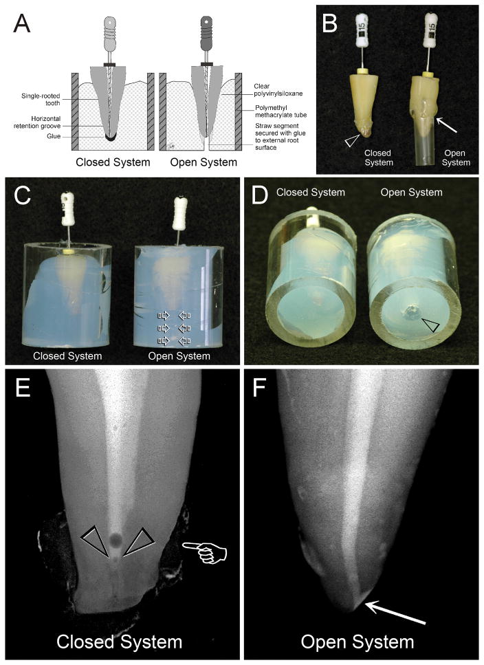
Introduction: This study examined the effect of vapor lock on canal debridement efficacy by testing the null hypothesis that there is no difference between a "closed" and an "open" system design in smear layer and debris removal by using a side-vented needle for irrigant delivery.

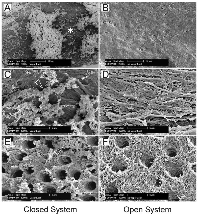
Methods: Roots in the closed system were sealed with hot glue and embedded in polyvinylsiloxane to restrict fluid flow through the apical foramen during cleaning and shaping. For the open system, the apical foramen was enlarged and connected to the external environment via a channel within the polyvinylsiloxane to permit unrestricted fluid flow. Smear and debris scores were evaluated by using scanning electron microscopy and analyzed by using Cochran-Mantel-Haenszel statistic.

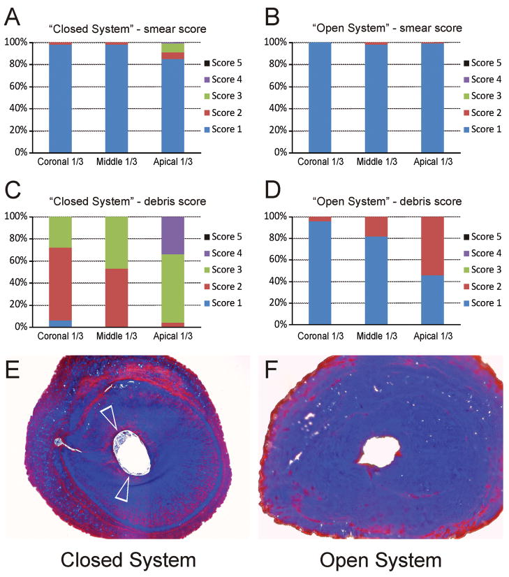
Results: No difference in smear scores was detected between the 2 systems at all canal levels. Significant differences in debris scores between the 2 systems were found at each canal level: coronal (P < .001), middle (P < .001), and apical (P < .001).

Conclusions: The null hypothesis was rejected; presence of an apical vapor lock effect adversely affects debridement efficacy. Thus, studies with unspecified or questionable mechanisms to restrict fluid flow through the apical foramen have to be interpreted with caution.


Figures

Fig. 1
Fig. 1
A. A schematic depicting the setups for the “Closed System” and “Open System” groups. B. The apical foramen was covered with hot flexible glue for the “Closed System” group, while a straw segment was secured with glue to the external root surface (arrow) for the “Open System” control group. C. Roots shown in Figure 1B were stabilized with clear PVS in Plexiglas tubes. For the control group, a piece of cotton was placed inside the straw (open arrows) prior to the insertion of the assembly into PVS. D. The straw opening in the control group was cleared of PVS to expose the fluid escape channel (open arrowhead). E. A micro-CT snapshot of a shaped canal from the “Closed System” group following delivery of cesium chloride. Radiopaque carbon paint was applied over the solidified glue surface to enhance the contrast (pointer). A vapor lock with an air bubble on top was produced along the apical end of the canal space (open arrowheads). F. A micro-CT snapshot of a shaped canal from the “Open System” group after the canal was filled with cesium chloride. The solution was able to reach the apical 0–2 mm of the canal space when the apical foramen remained open (arrow).
Fig. 2
Fig. 2
Representative scanning electron micrographs taken from different parts of the cleaned and shaped canal walls. Micrographs arranged on the left (A, C and E) and right (B, D and F) sides of the plate were derived from the “Closed System” and “Open System” groups, respectively. A. Along the apical 2 mm zone, the canal wall was sclerotic with minimal tubules (asterisk). For the “Closed System”, this zone was heavily covered with loose debris and some smear layer remnants. B. For the “Open System”, the apical 2 mm zone was sclerotic but devoid of the smear layer and had minimal debris. C. A high magnification view of the region marked by the asterisk in Fig. 2A. Particulate smear layer remnants (open arrowhead) were attached to the surface of the demineralized collagen matrix. D. A high magnification view of Fig. 2B showing a clean, smear layer-free and debris-free fibrous collagen matrix. No sign of dentinal tubules could be seen in this image. E. A high magnification image representative of the middle and coronal thirds of the canal wall in the “Closed System”. The dentinal tubules were mostly patent and devoid of smear plugs. However, smear layer remnants and particulate debris conglomerates (open arrowhead) could be seen adhering to the fibrous collagen matrix. F. A high magnification image in the middle and coronal thirds of the canal wall in the control group. Tufted collagen fibrils could be identified from the surface of the smear layer-depleted, BioPure MTAD-demineralized intertubular dentin. Minimal debris was present.
Fig. 3
Fig. 3
These effects could be seen from the summary of the smear score and debris score from different regions of the canal walls (Figs. A–D). A. Descriptive statistics of the distribution of smear scores from the coronal third, middle third and apical third of the canal wall in the “Closed System” group. For the apical third category, scores reflect the overall condition of the apical 0–5 mm part of the canal wall. A 5-level scoring system was used for evaluating the efficacy of smear layer removal: 1 = Smear layer is completely absent. Most tubules are patent and debris-free (coronal third and middle third), or occluded with sclerotic casts (apical third); 2 = Smear layer covering less than 25% of the canal wall and dentinal tubules; 3 = Smear layer evident in 25–50% of the canal surface and tubules; 4 = Smear layer evident in 50–75% of the canal surface and tubules; 5 = Smear layer covering 75–100% of the canal surface and tubules. B. Descriptive statistics of the distribution of smear scores in the “Open System” group. C. Descriptive statistics of the distribution of debris scores from in the “Closed System” group. For the apical third category, scores reflect the overall condition of the apical 0–5 mm part of the canal wall. A 5-level scoring system was used for evaluating the efficacy of debris removal: 1 = clean canal wall, only very few debris particles; 2 = few small conglomerations; 3 = many conglomerations, less than 50% of the canal wall covered; 4 = more than 50% of the canal wall covered with conglomerations; 5 = complete cover of the canal walls with conglomerations. D. Descriptive statistics of the distribution of debris scores in the “Open System” group. E. Masson’s trichrome-stained, light microscopy image of fixed, demineralized roots taken from 0.5–1 mm coronal to the anatomical apex. The periphery of the canal space in the “Closed System” group was filled with stained, demineralized debris (open arrowheads). F. Masson’s trichrome stained light microscopy section taken from a similar region of a root canal in the “Open System” group revealed a clean canal with no stained, demineralized debris.

References

    1. Schilder H. Cleaning and shaping the root canal. Dent Clin North Am. 1974;18:269–96. - PubMed
    1. Sjögren U, Figdor D, Persson S, Sundqvist G. Influence of infection at the time of root filling on the outcome of endodontic treatment of teeth with apical periodontitis. Int Endod J. 1997;30:297–306. - PubMed
    1. Nair PN. Pathogenesis of apical periodontitis and the causes of endodontic failures. Crit Rev Oral Biol Med. 2004;15:348–81. - PubMed
    1. Haapasalo M, Endal U, Zandi H, Coil JM. Eradication of endodontic infection by instrumentation and irrigation solutions. Endod Topics. 2005;10:77–102.
    1. Moser JB, Heuer MA. Forces and efficacy in endodontic irrigation systems. Oral Surg Oral Med Oral Pathol. 1982;53:425–8. - PubMed

Publication types

Substances