. 2010 Mar 24:4:33.
doi: 10.1186/1752-0509-4-33.

Automated characterization of cell shape changes during amoeboid motility by skeletonization

Affiliations

Automated characterization of cell shape changes during amoeboid motility by skeletonization

Yuan Xiong et al. BMC Syst Biol. .

Abstract

Background: The ability of a cell to change shape is crucial for the proper function of many cellular processes, including cell migration. One type of cell migration, referred to as amoeboid motility, involves alternating cycles of morphological expansion and retraction. Traditionally, this process has been characterized by a number of parameters providing global information about shape changes, which are insufficient to distinguish phenotypes based on local pseudopodial activities that typify amoeboid motility.

Results: We developed a method that automatically detects and characterizes pseudopodial behavior of cells. The method uses skeletonization, a technique from morphological image processing to reduce a shape into a series of connected lines. It involves a series of automatic algorithms including image segmentation, boundary smoothing, skeletonization and branch pruning, and takes into account the cell shape changes between successive frames to detect protrusion and retraction activities. In addition, the activities are clustered into different groups, each representing the protruding and retracting history of an individual pseudopod.

Conclusions: We illustrate the algorithms on movies of chemotaxing Dictyostelium cells and show that our method makes it possible to capture the spatial and temporal dynamics as well as the stochastic features of the pseudopodial behavior. Thus, the method provides a powerful tool for investigating amoeboid motility.


Figures

Figure 1
Figure 1
Skeleton representation of moving cells. A. The skeleton of a closed region is obtained by finding bitangential circles throughout the cell (three are shown in green). The centers of these circles (black dots) are joined to form the skeleton (red line segments within the region). B. Fluorescent image (B1) of a wild-type Dictyostelium cell chemotaxing towards the bottom along with the computed skeleton (B2) and overlay (B3). C. Similar representation for a DIC image. Scale bars represent 5 μm.
Figure 2
Figure 2
Boundary smoothing. A. Fluorescent image of a chemotaxing cell. B. The closed curve shows the edge of the segmented shape before smoothing; the line segments form the skeleton obtained from this shape. C. Smoothed boundary and resultant skeleton. D. Comparison of the original (grey) and post-boundary-smoothing (black) skeletons. Note that several branches deemed to arise from noise fluctuations in the image have disappeared.
Figure 3
Figure 3
Branch pruning. A. DIC image of a moving Dictyostelium cell in which the skeleton (B) shows three distinct major branches. Near the boundary, these branches may bifurcate and form smaller branches shorter than the length threshold pthreshold (insets). If the branch is independent; that is, it does not share a root with any other outer branch (middle insert, green branch), we remove it from the skeleton. Otherwise, if the branch shares a root with another branch (blue branches in all three insets), we either combine the two branches (if they are roughly the same length, i.e., the length of the longer branch divided by the shorter one is less than the ratio threshold r, three pairs of blue branches in three insets) or remove the shorter branch (when they are of significantly different lengths, i.e., the length ratio is no less than r, not shown). C. Skeleton after branch pruning. D. The real protrusion or retraction usually occurs when the branch terminal is close to the boundary (red). If the boundary is locally rounded (blue), the branch will be far away and it is unlikely that a pseudopodial activity happens there.
Figure 4
Figure 4
Dynamic skeletons. A. Two consecutive images of a chemotaxing Dictyostelium cell; A2 shows the latter frame. The images are 30 seconds apart. B. Cell boundaries and their respective pruned skeletons: Sn for the earlier frame and Sn+1 for the latter one. C. By comparing the regions in the two images, a difference map is obtained describing the deformation of the cell from one image to the other. White regions (formula image) are growing, while black regions (formula image
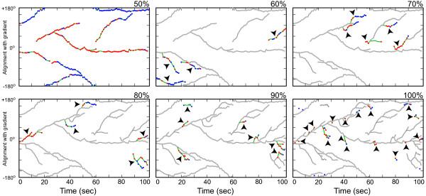
) are withdrawing. D. Branches of the skeleton in the latter frame (red lines) signal protrusion activities if they are pointing at regions in formula image, and branches of the skeleton in the earlier frame (blue lines) signal retractions if they are pointing at regions in formula image. The starting positions of these activities are decided by the points where Sn+1 or Sn intersects the boundary curve of the earlier frame (red dots for protrusions and blue dots for retractions). The size of an activity is calculated as the length of the part of associated branch that resides in the growing (L1 in D1) or withdrawing (L2 in D2) area. E. The relative angle of a protrusion (θ3) or retraction (θ4) is defined when the cell is moving in response to a gradient of chemoattractant, based on the center of the cell in the earlier frame (the black dot) and the starting point of the activity (red dot for protrusion and blue dot for retraction).
Figure 5
Figure 5
Individual pseudopods analysis. A-C. State and angle dynamics for pseudopods with consistent protrusions (A), consistent retractions (B) and protrusions followed by retractions (C). The movie was obtained courtesy of N. Andrew and R. H. Insall. The images show superimposed cell shapes (from the beginning of each pseudopod) and activity trajectories (red for protrusions, blue for retractions). The numbers represent the time (in seconds) from the beginning of the movie. The corresponding activity profiles relative to the chemoattractant gradient are plotted in D-F. In these plots red and blue dots represent protrusions and retractions, respectively, and the green lines join activities coming from the same pseudopod. G-J. The angle dynamics of all pseudopods superimposed by the directions of cell centroid (light-blue dots). Pseudopods with consistent protrusion pattern, consistent retraction pattern, protrusion followed by retraction pattern are highlighted in frame G-I, respectively. All the short-lived pseudopods are highlighted in J.
Figure 6
Figure 6
Hierarchy of pseudopod activities. Pseudopod activities as a function of time, hierarchically ranked. The panels show all the pseudopods that contribute from 50 to 100% of the cell's total pseudopodial activity. The color scheme of Figure 5D-F is applied to all the pseudopods not included in earlier panels. These pseudopods are also identified with arrow heads.
Figure 7
Figure 7
Protrusion angle distributions for different strains during chemotaxis. Protrusion angle histogram (green) fitted by a Gaussian curve (red line) for vegetative AX3 cells (A) and AX3:tsuA cells (B), both in the gradient of folic acid released from a needle [33], as well as those for developed AX2 cells (C) and developed AX2:dynhp cells (D), both in the gradient of cAMP released from a needle [34]. The Gaussian fittings yield different values of mean ± STD: -15.5° ± 90.3° for vegetative AX3 cells (A), 0.0° ± 29.1° for developed AX2 cells (C), -2.3° ± 62.8° for developed AX2:dynhp cells (D). The Gaussian fitting for vegetative AX3:tsuA cells does not converge (B). The comparisons of other pseudopod statistics between these strains are summarized in Table 3.
Figure 8
Figure 8
Localizations of myosin and Dynacortin in chemotaxing cells. Fluorescent images of a chemotaxing Dictyostelium cell expressing mCherry-dynacortin and GFP-myosin-II. A chemoattractant gradient was created using a micropipette needle on the left as previously described [34]. Small arrows placed near cell membrane point to the pseudopodial activities. The numbers at the right upper corners represent the time (in seconds) from the beginning of the movie. The scale bar represents 5 μm. B, D. Fluorescent intensity of mCherry-dynacortin (B) or GFP-myosin-II (D) as a function of time around the cell perimeter for the cell in panel A. The data is normalized between minimum (0) and maximum (1). C. Pseudopod activity as a function of time for the cell in panel A using the same color scheme as in Figure 5D-F. E. Cross-correlations between the two fluorescently-tagged proteins and protrusion or retraction activities as a function of time and angle. Left panels: averaged over 37 cells; right panels: averaged over 100 cells. F. Changes of local protrusion or retraction length in one frame as a function of the local intensity of GFP-myosin-II (100 cells, 4254 frames) or mCherry-dynacortin (37 cells, 1533 frames). Error bars represent standard errors.
Figure 9
Figure 9
Correlation analysis between pseudopodial activities and protein localization. Scatter plot between activity length (positive length implies a protrusion, negative length a retraction, measured in pixels) and dynacortin-mCherry (number of standard deviations above the mean fluorescence around each cell) for all activities both at the site of the activity (A) and 180° away (B). The correlation coefficient (ρ) for each plot is given. These data represent 3333 activities in 37 cells. C. Histogram for the correlation coefficients for each cell at the site of the activity (red) and 180° away (blue). D. Mean dynacortin-mCherry fluorescence at the sites of protrusions and retractions (error bars are SEM). E-H. Similar plots for myosin-II-GFP. These data represent 9019 activities in 100 cells.

Similar articles

Cited by

References

    1. Stossel TP. The E. Donnall Thomas Lecture, 1993. The machinery of blood cell movements. Blood. 1994;84(2):367–379. - PubMed
    1. Soll DR, Voss E, Wessels D, Kuhl S. In: Imaging Cellular and Molecular Biological Functions. Shorte SL, Frischknecht F, editor. Heidelberg: Springer-Verlag; 2007. Computer-Assisted Systems for Dynamic 3D Reconstruction and Motion Analysis of Living Cells; pp. 365–384. full_text.
    1. Machacek M, Danuser G. Morphodynamic profiling of protrusion phenotypes. Biophysical journal. 2006;90(4):1439–1452. doi: 10.1529/biophysj.105.070383. - DOI - PMC - PubMed
    1. Bosgraaf L, van Haastert PJ, Bretschneider T. Analysis of cell movement by simultaneous quantification of local membrane displacement and fluorescent intensities using Quimp2. Cell motility and the cytoskeleton. 2009;66(3):156–165. doi: 10.1002/cm.20338. - DOI - PubMed
    1. Maeda YT, Inose J, Matsuo MY, Iwaya S, Sano M. Ordered patterns of cell shape and orientational correlation during spontaneous cell migration. PloS one. 2008;3(11):e3734. doi: 10.1371/journal.pone.0003734. - DOI - PMC - PubMed

Publication types

LinkOut - more resources