

Analysis of the role of lead resistivity in specific absorption rate for deep brain stimulator leads at 3T MRI
- PMID: 20335090
- PMCID: PMC3145199
- DOI: 10.1109/TMI.2010.2040624
Analysis of the role of lead resistivity in specific absorption rate for deep brain stimulator leads at 3T MRI
Abstract
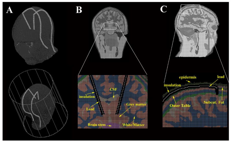
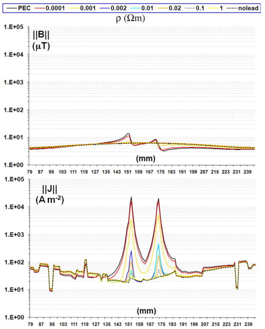
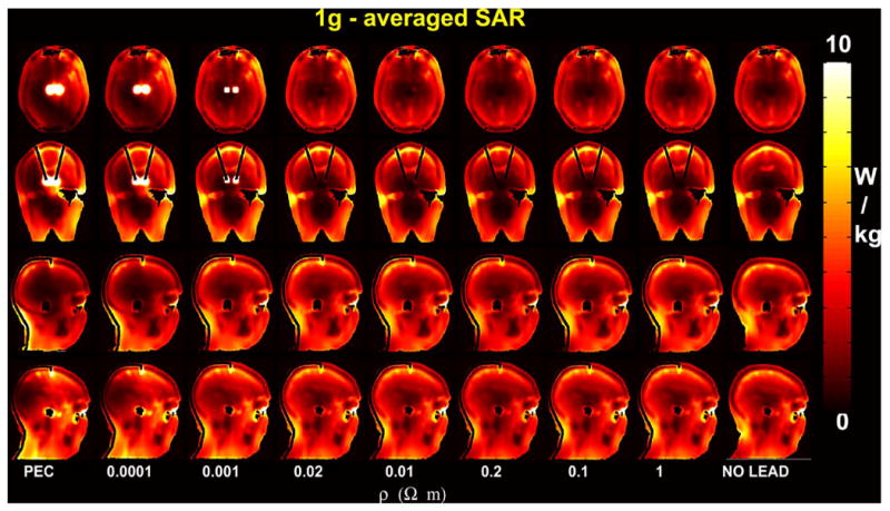
Magnetic resonance imaging (MRI) on patients with implanted deep brain stimulators (DBSs) can be hazardous because of the antenna-effect of leads exposed to the incident radio-frequency field. This study evaluated electromagnetic field and specific absorption rate (SAR) changes as a function of lead resistivity on an anatomically precise head model in a 3T system. The anatomical accuracy of our head model allowed for detailed modeling of the path of DBS leads between epidermis and the outer table. Our electromagnetic finite difference time domain (FDTD) analysis showed significant changes of 1 g and 10 g averaged SAR for the range of lead resistivity modeled, including highly conductive leads up to highly resistive leads. Antenna performance and whole-head SAR were sensitive to the presence of the DBS leads only within 10%, while changes of over one order of magnitude were observed for the peak 10 g averaged SAR, suggesting that local SAR values should be considered in DBS guidelines. With rho(lead) = rho(copper) , and the MRI coil driven to produce a whole-head SAR without leads of 3.2 W/kg, the 1 g averaged SAR was 1080 W/kg and the 10 g averaged SAR 120 W/kg at the tip of the DBS lead. Conversely, in the control case without leads, the 1 g and 10 g averaged SAR were 0.5 W/kg and 0.6 W/kg, respectively, in the same location. The SAR at the tip of lead was similar with electrically homogeneous and electrically heterogeneous models. Our results show that computational models can support the development of novel lead technology, properly balancing the requirements of SAR deposition at the tip of the lead and power dissipation of the system battery.
Figures


References
-
- Machado A, Rezai AR, Kopell BH, Gross RE, Sharan AD, Benabid AL. Deep brain stimulation for Parkinson's disease: Surgical technique and perioperative management. Movement Disorders. 2006 Jun;21:S247–258. - PubMed
-
- Benabid AL, Deuschl G, Lang AE, Lyons KE, Rezai AR. Deep brain stimulation for Parkinson's disease. Movement Disorders. 2006 Jun;21(no. Suppl 14):S168–170. - PubMed
-
- Baker KB, Tkach LA, Phillips MD, Rezai AR. Variability in RF-induced heating of a deep brain stimulation implant across MR systems. J Magn Reson Imag. 2006 Dec;24:1236–1242. - PubMed
-
- Arantes PR, Cardoso EF, Barreiros MA, Teixeira MJ, Goncalves MR, Barbosa ER, Sukwinder SS, Leite CC, Amaro E., Jr Performing functional magnetic resonance imaging in patients with Parkinson's disease treated with deep brain stimulation. Movement Disorders. 2006 Aug;21:1154–1162. - PubMed
-
- Rezai AR, Baker KB, Tkach JA, Phillips M, Hrdlicka G, Sharan AD, Nyenhuis J, Ruggieri P, Shellock FG, Henderson J. Is magnetic resonance imaging safe for patients with neurostimulation systems used for deep brain stimulation? Neurosurgery. 2005 Nov;57:1056–1062. - PubMed
Publication types
MeSH terms
Grants and funding
LinkOut - more resources
Full Text Sources
Other Literature Sources
Medical
Miscellaneous
