Review
. 2010 Jul;67(13):2163-72.
doi: 10.1007/s00018-010-0322-x. Epub 2010 Mar 25.

Contrasting models for kinetochore microtubule attachment in mammalian cells

Affiliations
Review

Contrasting models for kinetochore microtubule attachment in mammalian cells

Bruce F McEwen et al. Cell Mol Life Sci. 2010 Jul.

Abstract

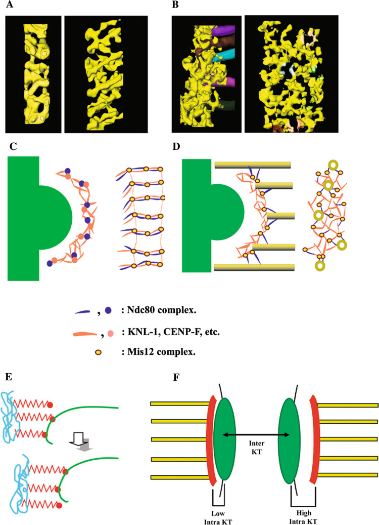
Kinetochore function is mediated through its interaction with microtubule plus ends embedded in the kinetochore outer plate. Here, we compare and evaluate current models for kinetochore microtubule attachment, beginning with a brief review of the molecular, biochemical, cellular, and structural studies upon which these models are based. The majority of these studies strongly support a model in which the kinetochore outer plate is a network of fibers that form multiple weak attachments to each microtubule, chiefly through the Ndc80 complex. Multiple weak attachments enable kinetochores to remain attached to microtubule plus ends that are continually growing and shrinking. It is unlikely that rings or "kinetochore fibrils" have a significant role in kinetochore microtubule attachment, but such entities could have a role in stabilizing attachment, modifying microtubule dynamics, and harnessing the energy released from microtubule disassembly. It is currently unclear whether kinetochores control and coordinate the dynamics of individual kinetochore microtubules.


Figures

Fig. 1
Fig. 1
Electron micrographs of unbound kinetochores from PtK1 cells. a Specimen prepared by conventional methods. b Specimen prepared by high-pressure freezing and freeze-substitution. The outer plate (op) and electron translucent middle layer (ml) are indicated in a. The outer plate appears as a fibrous mat (fm) in b and the corona appears distal to the fibrous mat as a zone of ribosome-exclusion. In b, the translucent middle layer is absent or very small, and the cytoplasm is smooth and continuous without the empty spaces seen in a. Reprinted from [18] by permission from Springer Science and Business Media
Fig. 2
Fig. 2
Molecular domains of the kinetochore and their relation to the physical structure. a Schematic illustration of the major molecular domains of the kinetochore and centromere. b Approximate locations of the molecular domains in a single slice from an electron tomographic reconstruction. The CCAN proteins are located in the region marked inner kinetochore (equivalent to the inner plate) and the KMN network is located in the region marked outer kinetochore (equivalent to the outer plate). The inner kinetochore forms a platform for the outer kinetochore, while the outer kinetochore binds kMTs. Scale bar in b = 250 nm. Reprinted from [19] by permission from Macmillan Publishers Ltd
Fig. 3
Fig. 3
Conformations of kMT plus ends in situ. a A gallery of 1.6-nm-thick slices from electron tomographic volumes of PtK1 kinetochores illustrating the range of bending observed in flared conformations of kMT plus ends. Putative kinetochore fibrils are indicated by arrows. b A similar gallery of 1.0-nm-thick slices with putative kinetochore fibrils indicated by arrows. Scale bars = 50 nm. a Modified from [15] with permission from Elsevier. b Reprinted from [50] with permission from Elsevier
Fig. 4
Fig. 4
Assembly of Dam1 rings on MTs. a Purified Dam1 complex is able to form rings around in vitro assembled MTs. b Complete decoration of the MTs is observed at higher concentrations of the Dam1 complex. Scale bar = 50 nm. Reprinted from [62] with permission from Elsevier
Fig. 5
Fig. 5
Illustrations of the outer plate network and kinetochore fibril models for kMT attachment. a, b Three-dimensional surface renderings of the outer plate in PtK1 kinetochores, based on the tracing of the outer plate fibrous components in kinetochores without (a) and with (b) kMTs. In each case, end-on views are shown on the left and en face views on the right with the outer plate network shown in yellow. Tracings of kMTs are shown in various colors in the edge view of the bound kinetochore in (b). The kMTs have been digitally removed from the en face view in (b), but shaded colors on the network fibers show where the corresponding kMTs insert into the outer plate. Note the dramatic reorganization of the outer plate upon kMT attachment. d Schematic illustrations corresponding to the surface renderings in a and b. A plausible arrangement for the KMN components is indicated by an assignment of shapes and colors in the key. e Illustration of the kinetochore fibril model. Kinetochore fibrils (shown in red) are thought to arise from chromatin in the inner kinetochore (shown in blue) and bind to the inner lumen of individual protofilaments of kMT plus ends (shown in green). In this way, the fibrils could restrict the curvature of the GDP lattice and harness some of the energy released from kMT disassembly for chromosome movement. f Illustration of how movement of the outer plate network relative to the underlying inner kinetochore could account for the intra-kinetochore stretch that is correlated with release of the spindle assembly checkpoint [71, 72]. Intra-kinetochore stretch is measured by labeling an inner kinetochore component (CENP-A) with GFP (location indicated by the green area in f), and an outer kinetochore component (Ndc80 or Mis12) with m-Cherry Red (location indicated by the red area in f). The hypothesized location of the outer plate (in red) in low and high intra-kinetochore stretch is indicated by “Low Intra KT” and “High intra KT” on the left and right sides of the figure. Inter-KT indicates the stretch between sister kinetochores, which is not correlated with checkpoint release. ad Adapted from [49] with permission from Macmillan Publishers Ltd. e Reprinted from [50] with permission from Elsevier. f Reprinted from [73] with permission from Rockefeller University Press

References

    1. Rieder CL, Salmon ED. The vertebrate cell kinetochore and its roles during mitosis. Trends Cell Biol. 1998;8:310–318. doi: 10.1016/S0962-8924(98)01299-9. - DOI - PMC - PubMed
    1. Maiato H, Deluca J, Salmon ED, Earnshaw WC. The dynamic kinetochore–microtubule interface. J Cell Sci. 2004;117:5461–5477. doi: 10.1242/jcs.01536. - DOI - PubMed
    1. Chan GK, Liu ST, Yen TJ. Kinetochore structure and function. Trends Cell Biol. 2005;15:589–598. doi: 10.1016/j.tcb.2005.09.010. - DOI - PubMed
    1. Tanaka K, Kitamura E, Kitamura Y, Tanaka TU. Molecular mechanisms of microtubule-dependent kinetochore transport toward spindle poles. J Cell Biol. 2007;178:269–281. doi: 10.1083/jcb.200702141. - DOI - PMC - PubMed
    1. Musacchio A, Salmon ED. The spindle-assembly checkpoint in space and time. Nat Rev Mol Cell Biol. 2007;8:379–393. doi: 10.1038/nrm2163. - DOI - PubMed

Publication types

LinkOut - more resources