Review
. 2010 Jun;3(5-6):385-407.
doi: 10.1002/jbio.200900087.

Scanning fiber endoscopy with highly flexible, 1 mm catheterscopes for wide-field, full-color imaging

Affiliations
Review

Scanning fiber endoscopy with highly flexible, 1 mm catheterscopes for wide-field, full-color imaging

Cameron M Lee et al. J Biophotonics. 2010 Jun.

Abstract

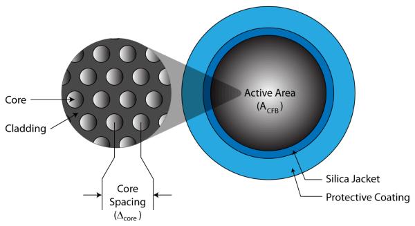
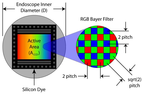
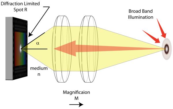
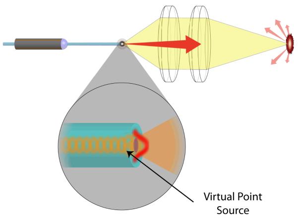
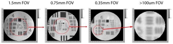
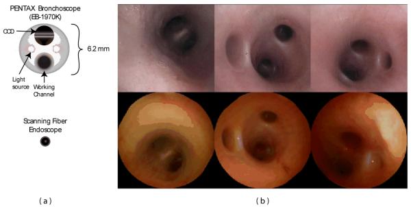
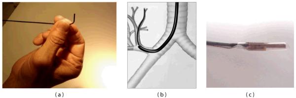
In modern endoscopy, wide field of view and full color are considered necessary for navigating inside the body, inspecting tissue for disease and guiding interventions such as biopsy or surgery. Current flexible endoscope technologies suffer from reduced resolution when device diameter shrinks. Endoscopic procedures today, using coherent fiber-bundle technology on the scale of 1 mm, are performed with such poor image quality that the clinician's vision meets the criteria for legal blindness. Here, we review a new and versatile scanning fiber-imaging technology and describe its implementation for ultrathin and flexible endoscopy. This scanning fiber endoscope (SFE) or catheterscope enables high-quality, laser-based, video imaging for ultrathin clinical applications, while also providing new options for in vivo biological research of subsurface tissue and high resolution fluorescence imaging.


Figures

Figure 1
Figure 1
Functional diagram of the SFE with the scanning illumination fiber moving in the spiral scan pattern. A magnified view of the co-axial scanner design is shown, which consists of the central singlemode optical fiber that is cantilevered from the tip of a tubular piezoelectric actuator, held by a mounting collar.
Figure 2
Figure 2
Electronic functional diagram of amplitude-modulated drive of the fiber scanner.
Figure 3
Figure 3
Optical collection methods: confocal, dual-clad and external large core fiber
Figure 4
Figure 4
Block diagram of the SFE color system with 4th channel for near infrared fluorescence.
Figure 5
Figure 5
Photograph of SFE system being used to image within a closed fist of the operator.
Figure 6
Figure 6
SFE bronchoscopic image frames from standard RGB imaging at 500-line images at 30 Hz (a) and the corresponding ESI image (b) that increases contrast of blue laser light over the red laser light, helping to differentiate blood vessels and inflamed tissue. SFE fluorescence image acquired on the red channel showing hypericin localization within a tumor of renal cell carcinoma (c). Blue and green laser illumination was used while a small fraction of the blue backscattered light was collected to form the background structural image.
Figure 7
Figure 7
Frame sequential imaging, diagnosis or therapy.
Figure 8
Figure 8
SFE video frame (left) of fluorescence microspheres (Nile-red FluoSphere, F-8819, Molecular Probes) embedded within a synthetic phantom of a bile duct. Optical spectral analysis (right) that shows the high laser illumination at 532 nm and fluorescence emission when collection optical fibers are connected to a spectrometer (USB2000-FL, Ocean Optics). SFE red channel detection range is illustrated on the spectral plot.
Figure 9
Figure 9
Fused coherent fiber bundle (CFB) cross sectional view
Figure 10
Figure 10
CCD and CMOS Illustration
Figure 11
Figure 11
Traditional Endoscope Optics
Figure 12
Figure 12
SFE Optics
Figure 13
Figure 13
Scan adaption for electronic zoom
Figure 14
Figure 14
SFE endoscope probes showing 9 mm rigid tip length of 1.2 mm diameter prototype and 18 mm capsule length of ∅6.4 mm diameter TCE. A front view of the distal end of the TCE is shown in (b) illustrating that the TCE is a standard SFE probe with collection fibers modified for capsule use. The gastroesophageal junction of a human subject is shown in single 500-line RGB image contrast (c) compared to post-processed ESI contrast of the same SFE image frame (d). The lighter esophageal tissue is more clearly differentiated from the red colored gastric mucosa in the ESI image. An image of the human vocal chords is shown in (e).
Figure 15
Figure 15
Diagrams of a conventional Pentax bronchoscope (EB-1970K) and SFE (a) and corresponding bronchoscopic images within the airways of a pig.
Figure 16
Figure 16
Additional features are incorporated into the SFE design to permit bronchoscopic examination of small peripheral airways include: a steering mechanism (a) and guidance system that is used to locate SFE by means of a miniature (0.30 mm) sensor.
Figure 17
Figure 17
Fundamental overview of different fiberscope types used in biomedical research. (a) CFB-based fiberscope, usually implemented as single-photon excitation wide-field type. An image of the sample S is propagated through the gradient-index objective lens GRIN-OL and the coherent fiber-bundle CFB and remotely detected using a CCD-chip behind a dichroic beam-splitter DC (green rays). Fluorescence excitation light travels to the sample in the reverse direction (blue rays). In principle, this type can also be used in combination with proximal (on the optical table) beam scanning for single- and two-photon excitation microscopy. (b) Scanning type fiberscope, usually implemented as single-photon or two-photon excitation microscope. Fluorescence excitation light (blue rays) is guided to the distal fiberscope head-piece via DC and through a single-mode fiber SMF and is focused onto S via GRIN-OL. Fluorescence emission light (green rays) is usually proximally detected by a photomultiplier tube PMT after traveling the reverse direction. Distal beam scanning is usually achieved by either resonant fiber scanners, or MEMS scanners. Fluorescence detection efficiencies can be improved with dual-clad fibers. (c) Scanning type fiberscope, usually implemented as two-photon excitation fiberscope. Dichroic beam-splitting occurs distally in a custom microprism arrangement that is part of GRIN-OL. Near-infrared fluorescence excitation photons (red rays) are guided through a photonic crystal fiber PCF that permits distorsion-free delivery of femtosecond pulses. Fluorescence emission photons from S are remotely detected by a PMT after traveling through a large-core fiber LCF for improved efficiencies.
Figure 18
Figure 18
Fiberscope data acquired from rat cerebellum. (a) Anatomical organization of the rat cerebellar cortex. Flat dendritic trees of Purkinje cells form parasagittal planes that appear as band-like structures when observed from above. (b) Region-of-interest (ROI) selection (colored areas) can be a semi-automated process based on independent component analysis (ICA). (c) Spontaneous ΔF/F traces that are color coded to match the ROI selections in (b). Scale bar is 15 μm. Reproduced with permission from [23].

References

    1. Seibel EJ. 1-mm catheterscope. Optical Fibers and Sensors for Medical Diagnostics and Treatment Applications VIII, Proc. SPIE. 2008;6852:685207–8.
    1. Hirschowitz BI, Curtiss LE, Peters CW, Pollard HM. Demonstration of a new gastroscope, the fiberscope. Gastroenterology. 1958;35(1):50. discussion 51-3. - PubMed
    1. Baillie J. The endoscope. Gastrointest Endosc. 2007;65(6):886–93. - PubMed
    1. Fujikura . FIA:Image Fiber. Fujikura; 2009.
    1. Sumitomo 2009 http://www.sumitomoelectricusa.com.

Publication types

LinkOut - more resources