. 2010 Feb 15;18(4):3444-55.
doi: 10.1364/OE.18.003444.

Implementation of a digital optical phase conjugation system and its application to study the robustness of turbidity suppression by phase conjugation

Affiliations

Implementation of a digital optical phase conjugation system and its application to study the robustness of turbidity suppression by phase conjugation

Meng Cui et al. Opt Express. .

Abstract

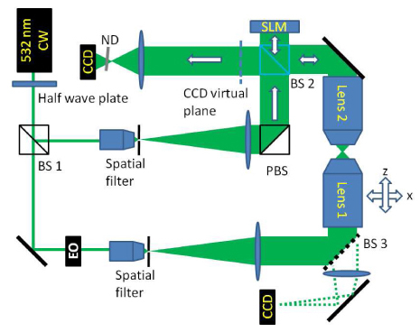
In this work, we report a novel high capacity (number of degrees of freedom) open loop adaptive optics method, termed digital optical phase conjugation (DOPC), which provides a robust optoelectronic optical phase conjugation (OPC) solution. We showed that our prototype can phase conjugate light fields with approximately 3.9 x 10(-3) degree accuracy over a range of approximately 3 degrees and can phase conjugate an input field through a relatively thick turbid medium (micro(s)l approximately 13). Furthermore, we employed this system to show that the reversing of random scattering in turbid media by phase conjugation is surprisingly robust and accommodating of phase errors. An OPC wavefront with significant spatial phase errors (error uniformly distributed from - pi/2 to pi/2) can nevertheless allow OPC reconstruction through a scattering medium with approximately 40% of the efficiency achieved with phase error free OPC.


Figures

Fig. 1
Fig. 1
The two elements of the DOPC system, a wavefront measurement device (sensor) and a spatial light modulator (actuator), are optically combined with a beam splitter. They function as a single system which can both measure an input wavefront and generate a phase conjugate output wavefront. (a) shows the wavefront measurement process wherein a reference wave interferes with the input signal. Their relative phase is controlled by an EO phase modulator. (b) shows the phase shaping process wherein the SLM modulates the incident reference wave.
Fig. 2
Fig. 2
Experimental setup of the DOPC system. The laser is a solid state CW laser at 532nm (Spectra-Physics, Excelsior Scientific 200mW). SLM, LCOS reflective spatial light modulator (Holoeye, LC-R 2500); CCD, CCD camera (ImagingSource DFK41BF02); PBS, polarizing beam splitter; BS1 and BS 2, non-polarizing beam splitter, ND, neutral density filter.
Fig. 3
Fig. 3
The procedure for mapping between the CCD and the SLM. (a) A mask was placed at the symmetry plane of the SLM. The mask was illuminated and imaged on CCD 1. (b), a phase pattern was displaced on the SLM, which was imaged on CCD 2. (c) The mask was illuminated and was imaged on CCD 2. (d) Experimentally measured SLM image. (e) Experimentally measured mask image.
Fig. 4
Fig. 4
Setup for testing the accuracy of DOPC. The laser is a solid state CW laser at 532nm. SLM, LCOS reflective spatial light modulator (Holoeye, LC-R 2500); CCD, CCD camera (ImagingSource DFK41BF02); PBS, polarizing beam splitter; BS, non-polarizing beam splitter. EO, electro-optic phase modulator (Thorlabs, EO-PM-NR-C4). Lens 1 and 2, objective lenses (Olympus, UPLFLN 100XO2, NA1.3), ND, neutral density filter.
Fig. 5
Fig. 5
(a) Lens 1 was shifted in the lateral direction. The beam exiting Lens 2 deviated from the original propagation direction. (b) Lens 1 was shifted in the axial direction. The beam incident on the DOPC system was either a converging or a diverging beam.
Fig. 6
Fig. 6
(a) The phase shifting holography measured wavefront when lens 1 was shifted laterally from the center position by 50 microns. (b) The measured wavefront when Lens 1 was shifted axially from the center position by 50 microns. (c) The DOPC reconstructed focus position as Lens 1was shifted laterally. (d) The DOPC reconstructed focus diameter as Lens 1 was shifted axially. (e) The measured reflected focus position variation when Lens 1 was shifted laterally. (f) The reflected focus size variation when Lens 1 was shifted axially.
Fig. 7
Fig. 7
(a) The DOPC measured phase profile. (b) DOPC reconstructed signal. The field of view is ~12 μm. (c) Control measurement with the phase of the SLM set to 0.
Fig. 8
Fig. 8
Theoretical calculation and experimental measurements of the reconstructed OPC signal dependence on the amount of phase error.

References

    1. Wenner M., “The most transparent research,” Nat. Med. 15(10), 1106–1109 (2009).10.1038/nm1009-1106 - DOI - PubMed
    1. Wang L. V., “Multiscale photoacoustic microscopy and computed tomography,” Nat. Photonics 3(9), 503–509 (2009).10.1038/nphoton.2009.157 - DOI - PMC - PubMed
    1. Vellekoop I. M., Mosk A. P., “Universal optimal transmission of light through disordered materials,” Phys. Rev. Lett. 101(12), 120601 (2008).10.1103/PhysRevLett.101.120601 - DOI - PubMed
    1. Yaqoob Z., Psaltis D., Feld M. S., Yang C., “Optical phase conjugation for turbidity suppression in biological samples,” Nat. Photonics 2(2), 110–115 (2008).10.1038/nphoton.2007.297 - DOI - PMC - PubMed
    1. Vellekoop I. M., Mosk A. P., “Focusing coherent light through opaque strongly scattering media,” Opt. Lett. 32(16), 2309–2311 (2007).10.1364/OL.32.002309 - DOI - PubMed

Publication types

MeSH terms