. 2010 Jul;31(21):5552-63.
doi: 10.1016/j.biomaterials.2010.03.051. Epub 2010 Apr 28.

The effects of intraspinal microstimulation on spinal cord tissue in the rat

Affiliations

The effects of intraspinal microstimulation on spinal cord tissue in the rat

Jeremy A Bamford et al. Biomaterials. 2010 Jul.

Abstract

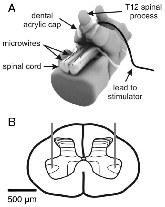
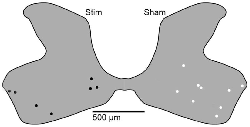
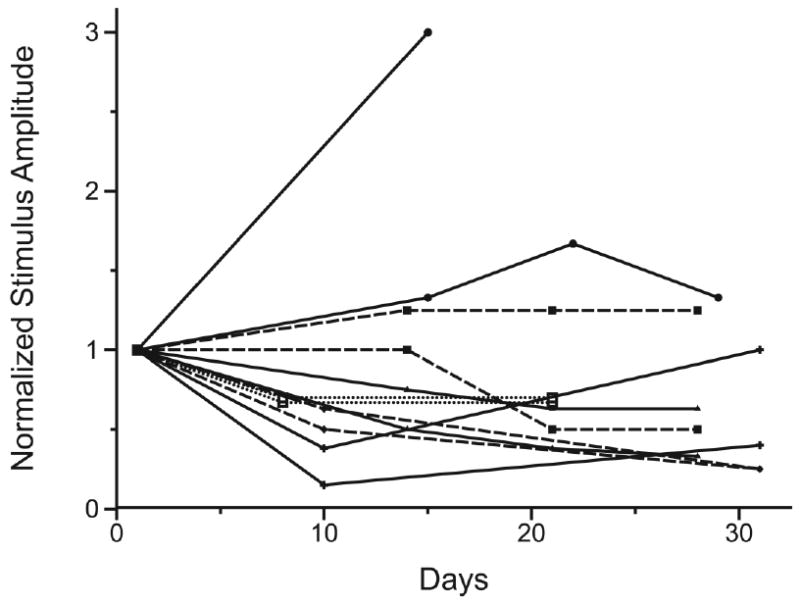
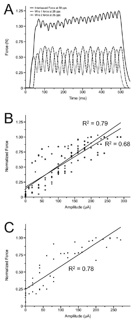
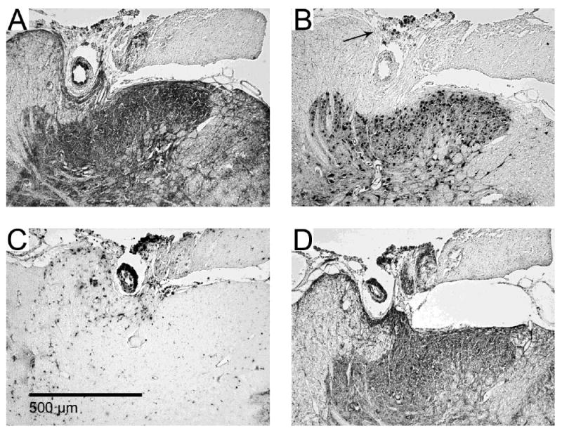
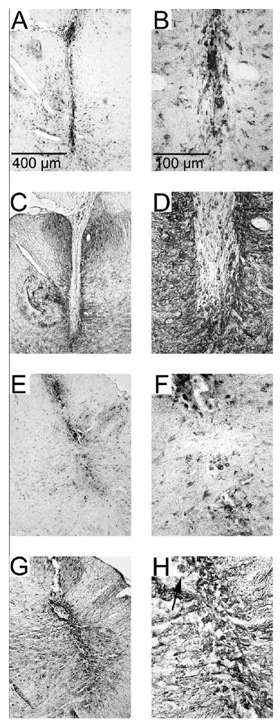
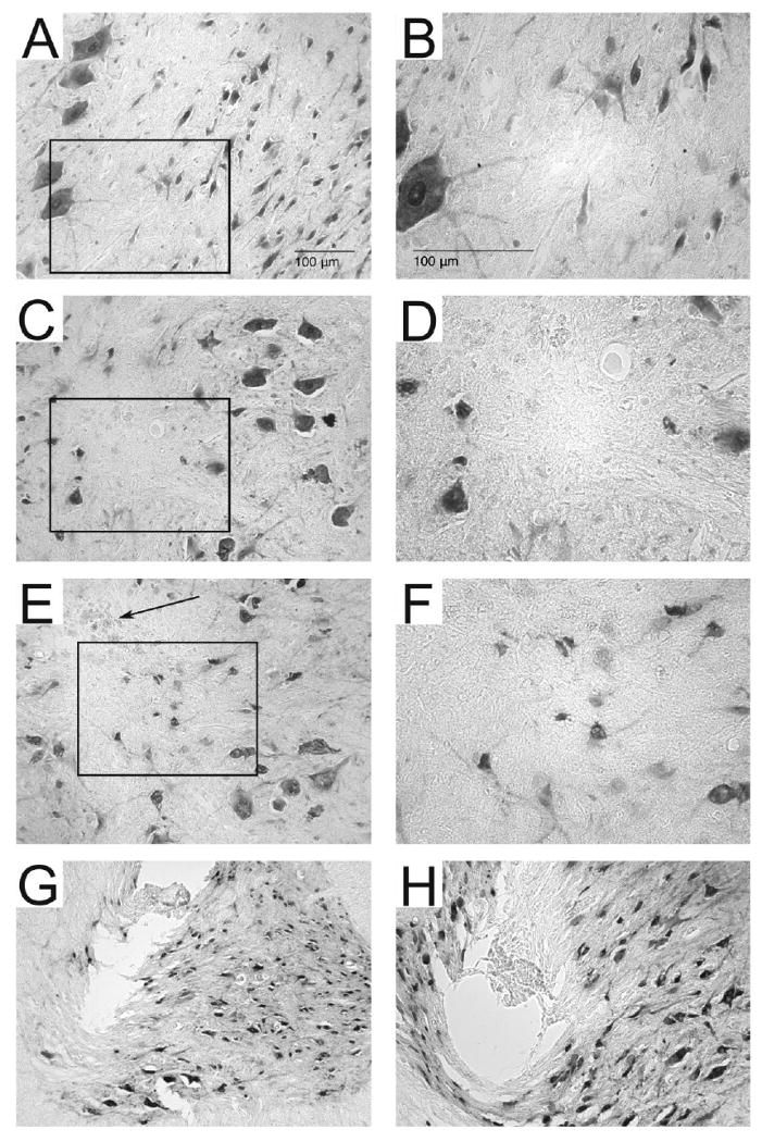
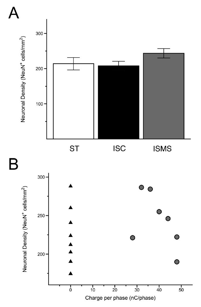
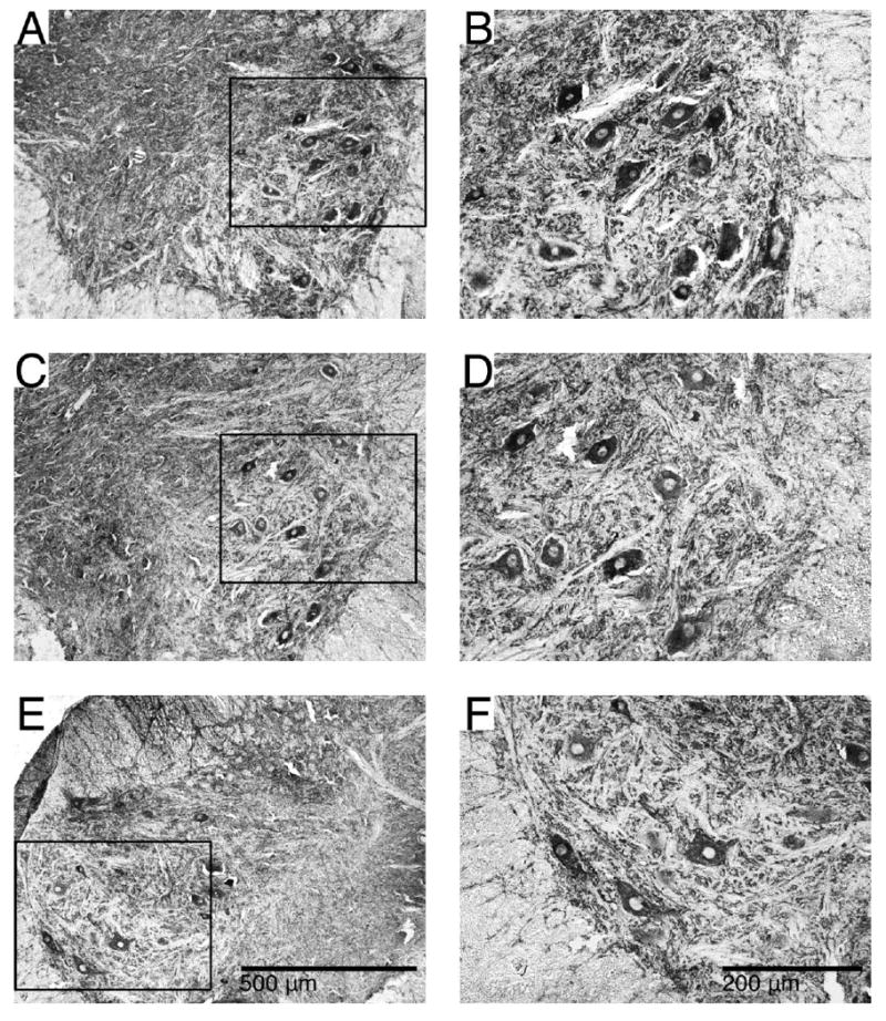
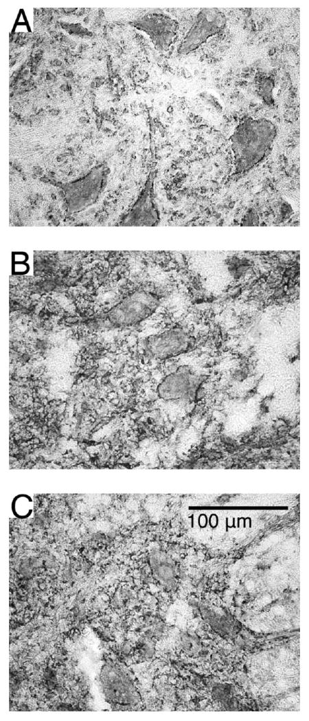
Intraspinal microstimulation (ISMS) involves the implantation of microwires into the spinal cord below the level of an injury to excite neural networks involved in the control of locomotion in the lower limbs. The goal of this study was to examine the potential spinal cord damage that might occur with chronic ISMS. We employed functional measures of force recruitment and immunohistochemical processing of serial spinal cord sections to evaluate any damage induced by spinal transection, implantation of ISMS arrays, and electrical stimulation of 4h/day for 30 days. Functional measurements showed no change in force recruitment following transection and chronic ISMS, indicating no changes to underlying neural networks. The implantation of sham intraspinal microwires produced a spatially-limited increase in the density of microglia/macrophages and GFAP+ astrocytes adjacent to the microwire tracks, indicating a persistent immune response. Most importantly, these results were not different from those around microwires that were chronically pulsed with charge levels up to 48nC/phase. Likewise, measurements of neuronal density indicated no decrease in neuronal cell bodies in the ventral grey matter surrounding ISMS microwires (243.6/mm2+/-35.3/mm2) compared to tissue surrounding sham microwires (207.8/mm2+/-38.8/mm2). We conclude that the implantation of intraspinal microwires and chronic application of ISMS are well tolerated by spinal cord tissue.


Figures

Figure 1
Figure 1. Schematic of the intraspinal implant
A laminectomy was performed at the T13 level in the rat to expose the lumbar enlargement for implantation of microwire arrays. (A) An example of an 8 microwire array is shown including the dental acrylic cap which secures the lead to the T12 spinous process. (B) Microwires with exposed tips are implanted bilaterally into the spinal cord with the tips targeting lamina IX in the ventral horn.
Figure 2
Figure 2. Summary of located microwire tips
The locations of stimulated and sham implanted microwire tips were identified in immunostained spinal cord tissue sections and a composite diagram was created to show their locations. We located 16 of 24 microwire tips, 9 from unpulsed microwires (shown in white) and 7 from pulsed microwires (shown in black). All tips were found within the grey matter of the ventral horn.
Figure 3
Figure 3. Activation thresholds from pulsed microwires during the 30 day stimulation period
ISMS thresholds for quadriceps muscle activation for the 12 stimulating microwires are shown normalized to their respective stimulus thresholds determined on the first day of stimulation. There was a significant decline in mean threshold amplitude from 118.2 μA ± 45.1 μA on the first day of stimulation to 67.8 μA ± 25.1 μA at the end of the stimulation period. The stimulus threshold for one microwire increased sharply before the microwire failed permanently on day 14. Of the remaining 11 microwires 8 had decreases in stimulus threshold, two had increases and one microwire had no overall change. Pairs of ipsilateral microwires in each animal are indicated by matching symbols and lines.
Figure 4
Figure 4. Force recruitment curves from intact and chronically spinalized and stimulated animals
(A) Examples are shown of forces recruited from individual ISMS microwires at 25 pps and from the resultant 50 pps product of interleaved stimulation through these microwires. (B) The relationship between normalized force and supra-threshold amplitude in intact animals from 6 individual microwires at 25 pps is shown in comparison to the same relationship generated by the resultant 50 pps product of interleaved stimulation in the same intact animals. (C) Following 30 days of chronic spinal transection and ISMS the relationship between normalized force and supra-threshold amplitude is shown.
Figure 5
Figure 5. Dorsal horn invagination by implanted microwires
Serial images from one example (of two total) of dorsal horn damage due to invagination of microwires running across the dorsal surface of the spinal cord. Immunohistochemical stains for (A) Map-2, (B), NeuN, (C) ED-1 and (D) GFAP. Encapsulation of the microwire occurred with some deformation of the dorsal grey matter. Some pieces of insulation pulled off from the microwires and can be seen in panel B as dark spots indicated by the arrow.
Figure 6
Figure 6. Pulsed and unpulsed microwire tracks
Examples of microwire tracks (A, C, E, G) and their tips (B, D, F, H). Unpulsed microwires (A, B, C, D) and pulsed microwires (E, F, G, H) displayed an ongoing inflammatory response as evidence by immunoreactivity for ED-1 (A, B, E, F). Encapsulation by a thin layer (< 50 μm) of GFAP immunoreactive astrocytes (C, D, G, H) was found along the entire track and at the microwire tip. The arrow in panel H indicates a piece of insulative material that was removed during explantation and was found in the microwire track.
Figure 7
Figure 7. Neuronal density around microwires and in control tissue
Shown are representative sections immunoreacted with NeuN in spinal control tissue (A, B), around an unpulsed microwire track (C, D) and around a pulsed microwire track (E, F). Boxed outlines in A, C, E indicate the enlarged areas in B, D, F. Panels C and E are representative of the microwire track most commonly observed following explantation and illustrate the difficulty associated with locating microwire tracks on tissue sections stained for NeuN. Darkly stained NeuN+ neurons can be seen surrounding the tracks of both pulsed and unpulsed microwire tracks. The microwire tracks themselves did not contain NeuN+ cells and often displayed bits of the insulation which were stripped from the microwire tip during explantation (arrow in panel E). Explantation of the microwire tips caused tearing of the tissue surrounding the microwire tracks in panels G and H. In panel G the tissue was pulled upwards along with the explanted microwire. In panel H the tissue subjacent to the microwire track can be seen to be compressed by the microwire, likely due to inadequate sharpening of the microwire tip.
Figure 8
Figure 8. Quantification of neuronal density
Determination of neuronal density was made by counting NeuN immunoreactive cells in the ventral horn of ST, ISC and ISMS spinal tissue. (A) Neuronal density was not decreased in ISC or ISMS groups as compared to the spinal transected control. (B) When plotted against charge per phase, the range of neuronal density was virtually identical between the ISC side (black triangles) and the unstimulated ISMS side (grey circles). There was no significant correlation between increasing charge per phase and a decrease in neuronal density on the ISMS side.
Figure 9
Figure 9. Cytoskeletal structure visualized with Map-2 immunoreactivity
Examples showing Map-2 immunoreactivity in the ventral horns of ST (A, B), ISMS (C, D) and ISC (E, F) groups. Black outlines in A, E, C indicate the enlarged areas in B, D, F. Strong staining of motoneurons and neurites in the ventral horn was seen including projections into the surrounding white matter. No apparent differences were noted between any of the groups.
Figure 10
Figure 10. Synaptic inputs to motoneurons visualized with synaptophysin immunoreactivity
Representative sections displaying synaptophysin immunoreactivity in the ventral horns of ST (A), ISMS (B) and ISC (C) groups. Punctate and discontinuous staining around motoneurons in the ventral horn was seen suggesting axosomatic inputs at these locations. No apparent differences were noted between any of the groups.

References

    1. Prochazka A, Mushahwar VK, McCreery DB. Neural prostheses. J Physiol. 2001;533:99–109. - PMC - PubMed
    1. Popovic DB. Neural Prostheses for Movement Restoration. In: Moore J, Zouridakis G, editors. Biomedical Technology and Devices Handbook. CRC Press LLC; 2004. pp. 28–1.
    1. Mushahwar VK, Jacobs PL, Normann RA, Triolo RJ, Kleitman N. New functional electrical stimulation approaches to standing and walking. J Neural Eng. 2007;4:S181–97. - PubMed
    1. Lau B, Guevremont L, Mushahwar VK. Strategies for generating prolonged functional standing using intramuscular stimulation or intraspinal microstimulation. IEEE Trans Neural Syst Rehabil Eng. 2007;15:273–85. - PubMed
    1. Saigal R, Renzi C, Mushahwar VK. Intraspinal microstimulation generates functional movements after spinal-cord injury. IEEE Trans Neural Syst Rehabil Eng. 2004;12:430–40. - PubMed

Publication types