. 2010 May;63(5):1315-22.
doi: 10.1002/mrm.22357.

B1 mapping by Bloch-Siegert shift

Affiliations

B1 mapping by Bloch-Siegert shift

Laura I Sacolick et al. Magn Reson Med. 2010 May.

Abstract

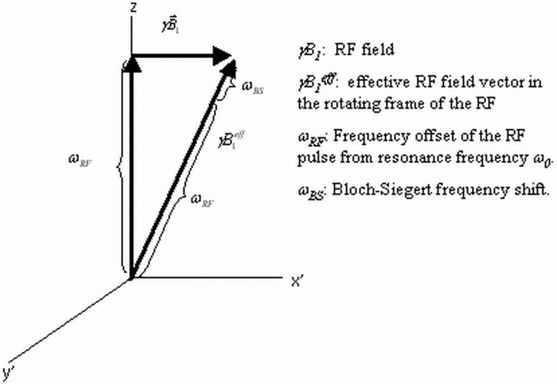
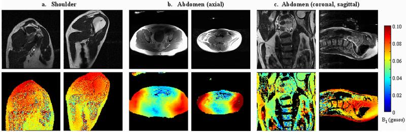
A novel method for amplitude of radiofrequency field (B1+) mapping based on the Bloch-Siegert shift is presented. Unlike conventionally applied double-angle or other signal magnitude-based methods, it encodes the B(1) information into signal phase, resulting in important advantages in terms of acquisition speed, accuracy, and robustness. The Bloch-Siegert frequency shift is caused by irradiating with an off-resonance radiofrequency pulse following conventional spin excitation. When applying the off-resonance radiofrequency in the kilohertz range, spin nutation can be neglected and the primarily observed effect is a spin precession frequency shift. This shift is proportional to the square of the magnitude of B1(2). Adding gradient image encoding following the off-resonance pulse allows one to acquire spatially resolved B(1) maps. The frequency shift from the Bloch-Siegert effect gives a phase shift in the image that is proportional to B(1)(2). The phase difference of two acquisitions, with the radiofrequency pulse applied at two frequencies symmetrically around the water resonance, is used to eliminate undesired off-resonance effects due to amplitude of static field inhomogeneity and chemical shift. In vivo Bloch-Siegert B(1) mapping with 25 sec/slice is demonstrated to be quantitatively comparable to a 21-min double-angle map. As such, this method enables robust, high-resolution B(1)(+) mapping in a clinically acceptable time frame.


Figures

Figure 1
Figure 1
B1 field in the rotating frame of the RF. The frame rotates at frequency ω0 + ωRF. In this frame, the B1 field is static, where as the spins rotate at ωRF. The Bloch-Siegert frequency shift ωBS is a constant field in this rotating frame along the effective RF field vector γB1eff.
Figure 2
Figure 2
Percentage error in B1 calculation as a function of B0 offset over a range of 1 kHz. The error is calculated from Eqns. 11 and 12, for RF pulses at off-resonance frequencies of 2, 4, 8 kHz.
Figure 3
Figure 3
Gradient and spin echo sequences, modified for B1 mapping. The gradient echo sequence has an 8 msec off-resonance Fermi pulse at off-resonance frequency ωRF following excitation. The spin echo sequence has two 6 msec off-resonance Fermi pulses. The first pulse is at off-resonance frequency ωRF and the second at −ωRF .
Figure 4
Figure 4
Normalized B1(t) and corresponding frequency excitation profile for an 8 msec Fermi pulse, and ωRF = 4 kHz.
Figure 5
Figure 5
Phase shift φBS vs. |B1| for an 8 msec Fermi pulse at 4 kHz. Simulated by the analytical expression of Eqn. 6, and numerical Bloch simulation.
Figure 6
Figure 6
Comparison of four RF pulses, all of 8 msec pulse length, at 4 kHz off-resonance, relative to water. The hard pulse, Fermi, adiabatic hyperbolic secant (with a time varying frequency sweep ωRF(t) of +/−2kHz around 4 kHz), and the adiabatic tanh/tan pulse (with a time varying frequency sweep ωRF(t) of +/−20kHz around 4 kHz). KBS (radians/gauss2) is calculated for these four pulses, as well as the frequency range that contains 99% of spin excitation. This Fermi pulse is used for all subsequent experiments shown here.
Figure 7
Figure 7
a. Double angle B1 map, calculated from two scans acquired with a 3.2 msec sinc pulse having flip angles of α = 60°, 2α = 120°, TE = 10 msec, TR = 5 sec. Slice thickness = 1 cm, 128×128 resolution. b. Gradient echo Bloch-Siegert B1 map, acquired with TE = 15 msec, TR = 70 msec (left), 2 sec. (right), 8 msec, +/−4 kHz Fermi pulse. c. Error between the two methods: Double Angle map / Bloch-Siegert map * 100% d. B1 maps acquired with the amplifier output at 0.33, 0.5, 0.75, 1.0, 1.5 * B1,peak, where B1,peak = 0.073 gauss B1 field produced at the center of the slice. The B1 maps are displayed rescaled to 0.073 gauss for comparison. e. Bloch-Siegert B1 maps of a saline phantom with three milk compartments acquired with the 8 msec Fermi pulse at off-resonance frequencies of 2, 4, 6, and 8 kHz relative to the water resonance.
Figure 8
Figure 8
a, b. Magnitude gradient echo images with 8 msec off-resonance Fermi pulse, ωRF = +/− 4 kHz. c. Same image acquisition, without the off-resonance pulse. d. Double angle B1 map, 128×128, slice thickness = 0.5 mm, TE = 12 msec, TR = 3 sec. Flip angles α = 45° 2α = 90°. e. Bloch Siegert map calculated from the phase difference between images a. and b. The peak B1 of the Bloch-Siegert map was twice the peak B1 used in the double angle map. Resolution 128×128, slice thickness = 0.5 mm, TE = 12 msec, TR = 100 msec, off resonance pulse: 8 msec Fermi, ωRF = +/− 4 kHz.
Figure 9
Figure 9
a. Double angle B1 map, resolution 128×128, slice thickness = 0.5 mm, TE = 12 msec, TR = 5 sec. Flip angles α = 60° 2α = 120°. b. Gradient echo Bloch-Siegert map, resolution 128×128, slice thickness = 0.5 mm, TE = 12 msec, TR = 100 msec, off resonance pulse: 8 msec Fermi, ωRF = +/− 4 kHz.
Figure 10
Figure 10
Spin echo Bloch-Siegert B1 maps, acquired with two 6 msec, +/− 4 kHz off-resonance Fermi pulses, applied symmetrically around a 3.2 msec sinc refocusing pulse. The Fermi pulses had the same peak B1 as the excitation pulse. TE = 28 msec, TR = 200 msec, resolution = 128×128, slice thickness = 1 cm. a. Shoulder, two subjects, taken with GE DVMR whole body transmit/receive coil. b. Abdomen, axial orientation two subjects, taken with whole body transmit, GE 8-channel torso receive array. c. Abdomen, sagittal and coronal orientations.

References

    1. Katscher U, Börnert P, Leussler C, van den Brink JS. Transmit SENSE. Magn Reson Med. 2003;49:144–150. - PubMed
    1. Zhu Y. Parallel excitation with an array of transmit coils. Magn Reson Med. 2004;51:775–784. - PubMed
    1. Xu D, King KF, Zhu Y, McKinnon GC, Liang ZP. Designing multichannel, multidimensional, arbitrary flip angle RF pulses using an optimal control approach. Magn Reson Med. 2008;59:547–560. - PMC - PubMed
    1. Warntjes JB, Leinhard OD, West J, Lundberg P. Rapid magnetic resonance quantification on the brain: Optimization for clinical usage. Magn Reson Med. 2008;60:320–329. - PubMed
    1. Hornak JP, Szumowski J, Bryant RG. Magnetic field mapping. Magn Reson Med. 1988;6:158–163. - PubMed

Publication types

MeSH terms