. 2010 Jul 15;190(2):258-70.
doi: 10.1016/j.jneumeth.2010.04.031. Epub 2010 May 8.

Neuroelectromagnetic forward head modeling toolbox

Affiliations

Neuroelectromagnetic forward head modeling toolbox

Zeynep Akalin Acar et al. J Neurosci Methods. .

Abstract

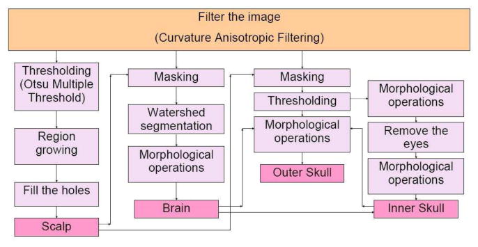
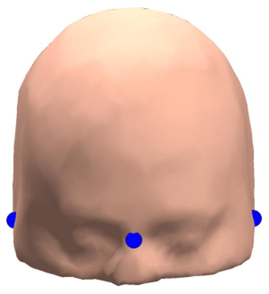
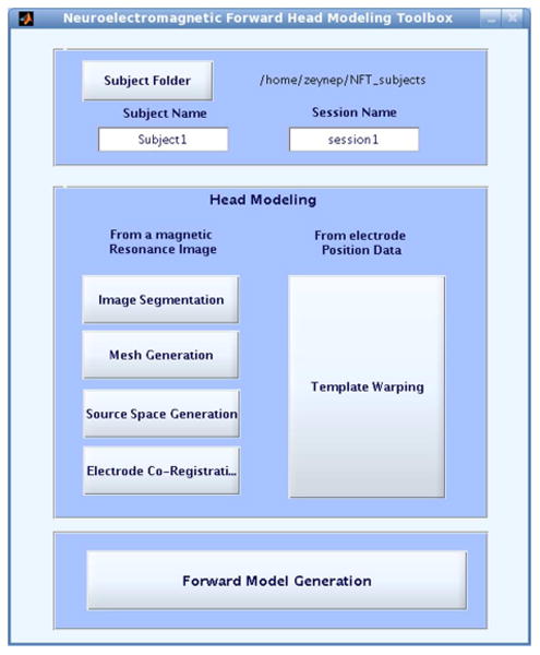
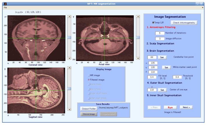
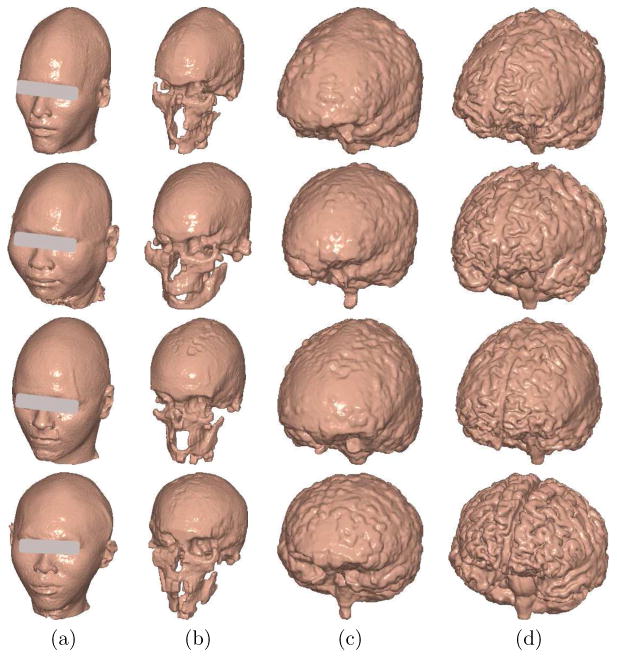
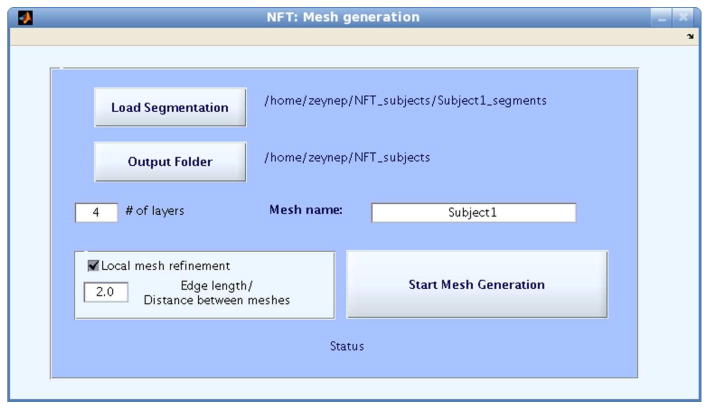
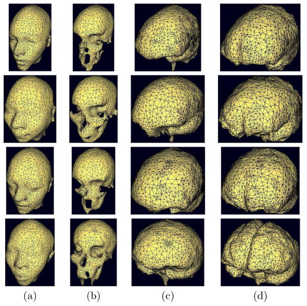
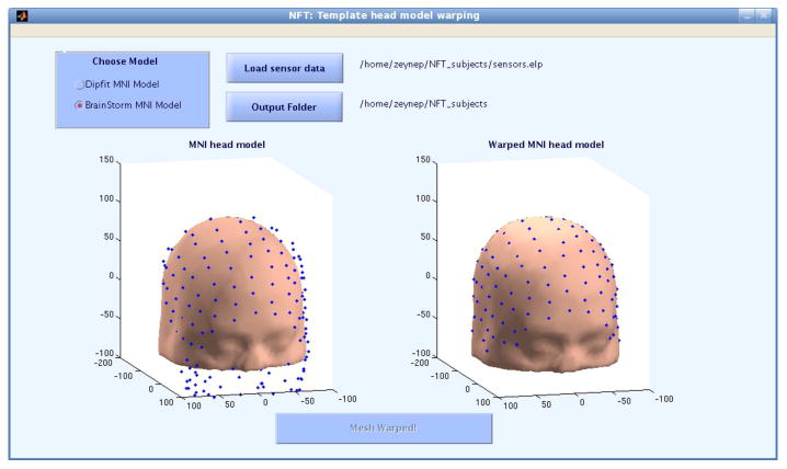
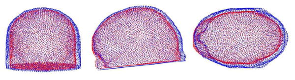
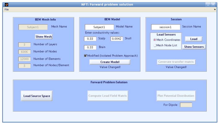
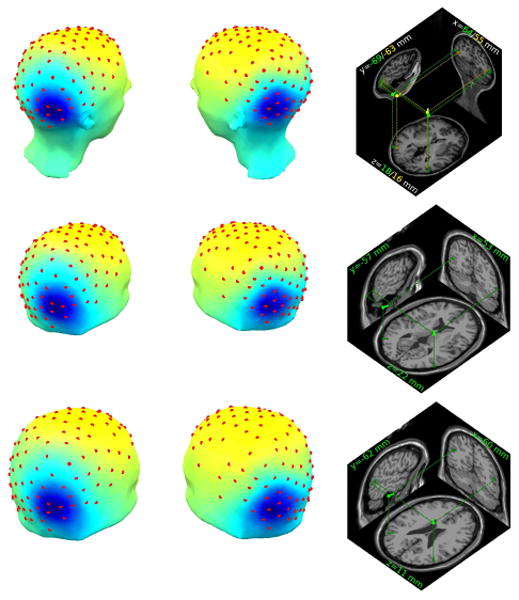
This paper introduces a Neuroelectromagnetic Forward Head Modeling Toolbox (NFT) running under MATLAB (The Mathworks, Inc.) for generating realistic head models from available data (MRI and/or electrode locations) and for computing numerical solutions for the forward problem of electromagnetic source imaging. The NFT includes tools for segmenting scalp, skull, cerebrospinal fluid (CSF) and brain tissues from T1-weighted magnetic resonance (MR) images. The Boundary Element Method (BEM) is used for the numerical solution of the forward problem. After extracting segmented tissue volumes, surface BEM meshes can be generated. When a subject MR image is not available, a template head model can be warped to measured electrode locations to obtain an individualized head model. Toolbox functions may be called either from a graphic user interface compatible with EEGLAB (http://sccn.ucsd.edu/eeglab), or from the MATLAB command line. Function help messages and a user tutorial are included. The toolbox is freely available under the GNU Public License for noncommercial use and open source development.


Figures

Figure 1
Figure 1
The segmentation algorithm used in NFT. Scalp, brain, outer skull, and inner skull are segmented using filtering, thresholding, region growing, morphologic operations, and watershed segmentation.
Figure 2
Figure 2
The nasion and left and right preauricular points shown on an MNI head model.
Figure 3
Figure 3
The NFT main user interface. This window is divided into three panels. The top panel is used to select the working folder and to name the subject and session. The lower panel is the head modeling panel. The lowest panel in the main menu of NFT cues forward model generation.
Figure 4
Figure 4
The NFT head tissue segmentation interface. When a T1-weighted MR image is loaded, anisotropic filtering, scalp, brain, outer skull, and inner skull segmentation are performed.
Figure 5
Figure 5
Segmentation results showing (a) scalp, (b) skull, (c) CSF and (d) brain volumes computed from four subject MR head images acquired using a 3-Tesla GE scanner.
Figure 6
Figure 6
The NFT mesh generation user interface. The mesh generation module uses the results of the segmentation and outputs either three-layer or four-layer BEM head meshes.
Figure 7
Figure 7
BEM models of the scalp, skull, csf and the brain for four subjects: (a) scalp mesh, (b) skull mesh, (c) CSF mesh, (d) brain mesh generated for the volumes shown in Figure 5.
Figure 8
Figure 8
The NFT user interface for warping a template head model to measured 3-D electrode locations.
Figure 9
Figure 9
Three views of the nodes of the template mesh (blue) and the warped mesh (red). The warped mesh fits the electrode locations.
Figure 10
Figure 10
The NFT BEM construction user interface has four panels: (Upper panels) Load a mesh, Load or generate BEM meshes, Load or generate transfer matrices. (Lower panel) Predict scalp potentials produced by given dipole(s).
Figure 11
Figure 11
Scalp projections (two left columns) and equivalent dipole source locations (right column) of two independent components extracted from a 140-electrode EEG recording by infomax ICA. Top row: Scalp maps and equivalent dipole positions computed using the individual subject MR-based BEM head models, (green dipoles) four-layer and (yellow dipoles) three-layer. Middle row: Scalp maps and equivalent dipole positions in the electrode position-warped standard three-layer MNI head model. Bottom row: Scalp maps and equivalent dipole positions based on electrode positions warped to the standard three-layer MNI head model. Slices shown are nearest to the (left posterior) equivalent dipole positions; their computed Talaraich locations are shown (green/yellow lettering).

Similar articles

Cited by

References

    1. Acar CE, Gençer NG. Forward problem solution of esi using FEM and BEM with quadratic isoparametric elements. Proc of IEEE EMBS Conf 1999 Sep;
    1. Akalin Acar Z. PhD Thesis. University of Middle East Technical University; Ankara: 2005. Electro-Magnetic Source Imaging Using Realistic Head Models.
    1. Akalin-Acar Z, Gençer NG. An advanced boundary element method (BEM) implementation for the forward problem of electromagnetic source imaging. Physics in Medicine and Biology. 2004;49:5011–5028. available at http://www.eee.metu.edu.tr/metu-fp/ - PubMed
    1. Akalin Acar Z, Makeig S. Neuroelectromagnetic forward modeling toolbox. Proc. of IEEE EMBC; Vancouver, CA: 2008. - PubMed
    1. Ataseven Y, Akalin-Acar Z, Acar CE, Gençer NG. Parallel implementation of the accelerated bem approach for emsi of the human brain. Med Biol Eng Comput. 2008;46:671–679. - PubMed

Publication types