. 2010 Jun 16;29(12):2037-47.
doi: 10.1038/emboj.2010.95. Epub 2010 May 11.

Structural basis for the assembly and gate closure mechanisms of the Mycobacterium tuberculosis 20S proteasome

Affiliations

Structural basis for the assembly and gate closure mechanisms of the Mycobacterium tuberculosis 20S proteasome

Dongyang Li et al. EMBO J. .

Abstract

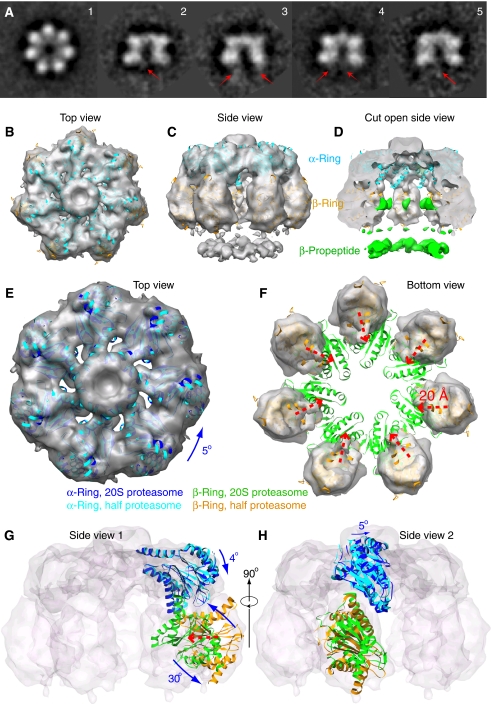
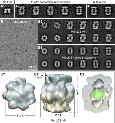
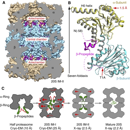
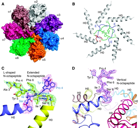
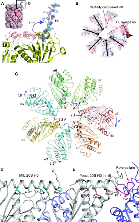
Mycobacterium tuberculosis (Mtb) possesses a proteasome system analogous to the eukaryotic ubiquitin-proteasome pathway. Mtb requires the proteasome to resist killing by the host immune system. The detailed assembly process and the gating mechanism of Mtb proteasome have remained unknown. Using cryo-electron microscopy and X-ray crystallography, we have obtained structures of three Mtb proteasome assembly intermediates, showing conformational changes during assembly, and explaining why the beta-subunit propeptide inhibits rather than promotes assembly. Although the eukaryotic proteasome core particles close their protein substrate entrance gates with different amino terminal peptides of the seven alpha-subunits, it has been unknown how a prokaryotic proteasome might close the gate at the symmetry axis with seven identical peptides. We found in the new Mtb proteasome crystal structure that the gate is tightly sealed by the seven identical peptides taking on three distinct conformations. Our work provides the structural bases for assembly and gating mechanisms of the Mtb proteasome.


Conflict of interest statement

The authors declare that they have no conflict of interest.

Figures

Figure 1
Figure 1
The 3D cryo-EM structure of the Mtb half proteasome. (A) A gallery of 2D class averages of the cryo-EM images of the Mtb half proteasome particles. The red arrows in the side views (panels 2–5) indicate averaged residual density of the flexible β-propeptides located at the bottom under the β-ring. (BD) Surface rendered cryo-EM 3D map of the Mtb half proteasome docked individually with the α-subunit (in cyan) and β-subunit (in brown) crystal structures in the top, side, and cut-open views. The EM density map is shown partially transparent. The discontinuous densities, coloured green in the cut-open view, are attributed to the flexible β-propeptides, and disappear at display threshold higher than 1.4 σ (D). (E, F) Computationally segmented α-ring (E) and β-ring electron density (F), superimposed with individually docked α-subunits (E, cyan) and β-subunits (F, yellow). Also superimposed are the α-ring (in blue) and β-ring structure (in green) of the mature Mtb 20S proteasome to illustrate the required structural re-arrangement. (G, H) Two orthogonal side views with electron density map shown as transparent surface rendering in grey. One α-subunit and one β-subunit structure in half proteasome and full proteasome positions are shown in carton representation. (EH) The translation and rotation of the individual α- and β-subunits in the Mtb half proteasome required for reaching the full Mtb 20S proteasome structure. See text for details.
Figure 2
Figure 2
A novel proteasome assembly intermediate as shown by cryo-EM and image classification. (A) A comparison of the side views of the freshly purified Mtb WT half proteasome (left panel, A1); in vitro conversion intermediates (middle panel, A2); and the fully assembly mature Mtb 20S proteasome (right panel, A3). (B) Cryo-EM characterization of the inhibitor-treated and in vitro assembled 20S proteasome intermediate (20S IM-I). The left panel (B1) shows a raw micrograph of the 20S IM-I embedded in vitreous ice, and the right panels show the reference-free 2D averages of the 20S IM-I (B2, top) and the purified 20S mature particles (B3, top). The corresponding reprojections from the 3D reconstructions are shown in the bottom panels for comparison (b2 bottom, the Mtb 20S IM-I; b3 bottom, the Mtb 20S mature proteasome). (C) Surface-rendered, 20% transparent top, side, and cut-open views of the cryo-EM map of the Mtb 20S IM-I at ∼25 Å resolution. The atomic model of the half 20S, derived from docking the α- and β-subunits into 3D cryo-EM map of the Mtb half proteasome, fits well in the density of the Mtb 20S IM-I. The β-propeptide densities, not resolved in the low-resolution map, is likely inside the central chamber, as indicated by a green oval in (C3).
Figure 3
Figure 3
The β-propeptide is ordered and ascended to the antechambers in the 20S T1A mutant proteasome (20S IM-II). (A) The crystal structure of the Mtb 20S IM-II shown in a cut-open side view. The β-propepetides are shown as ribbons in magenta, and the α- and β-rings are rendered in surface view and shown in brown and cyan, respectively. (B) Superposition of one α/β heterodimer of 20S IM-II (in yellow and cyan, respectively) with that of the mature Mtb 20S proteasome (in grey). The β-propeptide is shown in magenta. The dashed curves indicate unresolved residues. (C) Proposed structural changes accompanying the assembly of the Mtb 20S proteasome, starting from the half proteasome to the metastable 20S assembly intermediate I (20S IM-I), towards the assembled but immature proteasome intermediate II as represented by the T1A mutant structure (20S IM-II), and finally to the mature 20S proteasome. The β-propeptides are illustrated in green.
Figure 4
Figure 4
The Mtb proteasome has a tightly closed gate in the crystal structure of the T1A mutant 20S proteasome. (A) A space-filling surface view of the T1A mutant 20S proteasome shows that the substrate entrance channel in the centre of the top view is totally sealed. (B) Ribbon representation of the end structure of the T1A mutant 20S. The α-octapeptides take the ‘E' (coloured in blue) and ‘L' conformation (coloured in green) alternatively, except for the last one that protrudes upwards (labelled as ‘V' conformation, coloured in red), being almost perpendicular to the end surface of the Mtb 20S cylinder. (C) The 2Fo−Fc electron density of the α-octapeptides in two adjacent α-subunits rendered at 1.0 σ. The ‘L' configuration is in green, and the ‘E' configuration in purple. This picture is viewed from the top of the proteasome cylinder. Note residue Phe-3 is modelled as Ala-3 because of the absence of the side chain density. (D) The α-octapeptide that assumes the up-standing (‘V') conformation. Superimposed in purple is its 2Fo−Fc density contoured at 1.0 σ. The residue Ser-2 is modelled as Ala-2 because of the absence of the side chain density. The picture is viewed from the side of the proteasome cylinder.
Figure 5
Figure 5
The H0 helix in one α-subunit is displaced in the crystal structure of the Mtb 20SOG. (A) The electron density map of the displaced H0 helix, which is shown in the yellow stick-and-ball mode. The normal H0 position is shown in the grey stick-and-ball mode. The electron density map was calculated using a model with H0 in its normal position. The green and red meshes are Fo−Fc different density map contoured at ±3.0 σ, respectively, and the blue mesh is 2Fo−Fc electron density map contoured at 1.0 σ. Inserted at the top left corner is a surface representation of the Mtb 20SOG. (B) Top surface view of the Mtb 20SOG. The upward swinging of H0 helix in one α-subunit (dashed and solid red arrows) results in partial disorder of the H0 in its neighbouring α-subunit (dashed red arrow). (C) Multiple subunit movements in the α-ring of the 20SOG structure (in colour) as shown by comparing with the WT 20S α-ring (in grey). The α-subunit harbouring the displaced H0 helix (labelled α1) shifted outwards by ∼2 Å (the red arrow head), and rotated clockwise 2° (the blue curved arrow). In response to the outward movement of the α1-subunit the neighbouring α2-, α7-, and α6-subunits shifted towards the centre (the red arrows). Finally, responding to the changes at the right side of the α-ring (α1, α2, α6, and α7), the α5 and α3 at the left side of the ring each slightly rotated in an opposite direction, and the α4-subunit moved outwards by 2 Å. (D) The interactions of the H0 helix with the underlying structure at its normal position in the Mtb 20S proteasome as compared with the H0 helix in the α5-subunit of the yeast 20S proteasome (E). The reverse turn in the yeast α-subunit, which is absent in the Mtb α-subunit, is shown in purple in (E).

References

    1. Adams J (2003) The proteasome: structure, function, and role in the cell. Cancer Treat Rev 29: 3–9 - PubMed
    1. Arendt CS, Hochstrasser M (1999) Eukaryotic 20S proteasome catalytic subunit propeptides prevent active site inactivation by N-terminal acetylation and promote particle assembly. EMBO J 18: 3575–3585 - PMC - PubMed
    1. Borissenko L, Groll M (2007) 20S proteasome and its inhibitors: crystallographic knowledge for drug development. Chem Rev 107: 687–717 - PubMed
    1. Brunger AT (2007) Version 1.2 of the Crystallography and NMR system. Nat Protoc 2: 2728–2733 - PubMed
    1. da Fonseca PC, Morris EP (2008) Structure of the human 26S proteasome: subunit radial displacements open the gate into the proteolytic core. J Biol Chem 283: 23305–23314 - PMC - PubMed

Publication types

MeSH terms

Substances