Nanomedicine for the reduction of the thrombogenicity of stent coatings
- PMID: 20463940
- PMCID: PMC2865019
- DOI: 10.2147/ijn.s7596
Nanomedicine for the reduction of the thrombogenicity of stent coatings
Abstract
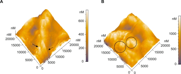
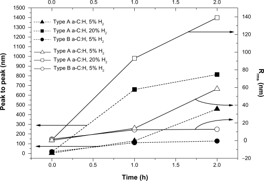
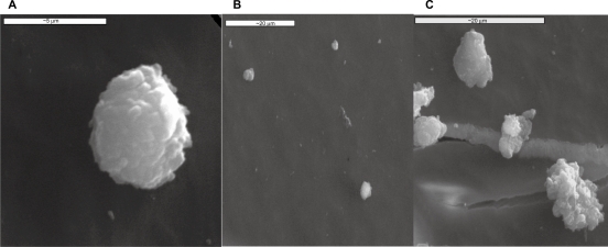
The treatment of patients with drug-eluting stents (DES) continues to evolve with the current emergence of DES technology that offers a combination of pharmacological and mechanical approaches to prevent arterial restenosis. However, despite the promising short-term and mid-term outcomes of DES, there are valid concerns about adverse clinical effects of late stent thrombosis. In this study, we present an example of how nanomedicine can offer solutions for improving stent coating manufacturing, by producing nanomaterials with tailored and controllable properties. The study is based on the exploitation of human platelets response towards carbon-based nanocoatings via atomic force microscope (AFM). AFM can facilitate the comprehensive analysis of platelets behavior onto stent nanocoatings and enable the study of thrombogenicity. Platelet-rich plasma from healthy donors was used for the real-time study of biointerfacial interactions. The carbon nanomaterials were developed by rf magnetron sputtering technique under controllable deposition conditions to provide favorable surface nanotopography. It was shown that by altering the surface topography of nanocoatings, the activation of platelets can be affected, while the carbon nanocoatings having higher surface roughness were found to be less thrombogenic in terms of platelets adhesion. This is an actual solution for improving the stent coating fabrication.
Keywords: atomic force microscopy platelets nanotechnology; carbon coating; stents nanomedicine.
Figures

Similar articles
-
Novel nanostructured biomaterials: implications for coronary stent thrombosis.Int J Nanomedicine. 2012;7:6063-76. doi: 10.2147/IJN.S34320. Epub 2012 Dec 17. Int J Nanomedicine. 2012. PMID: 23269867 Free PMC article.
-
Reduced thrombogenicity of nitinol stents--in vitro evaluation of different surface modifications and coatings.Biomaterials. 2006 Feb;27(4):643-50. doi: 10.1016/j.biomaterials.2005.06.004. Epub 2005 Aug 10. Biomaterials. 2006. PMID: 16095686
-
Atomic force microscopy probing platelet activation behavior on titanium nitride nanocoatings for biomedical applications.Nanomedicine. 2009 Mar;5(1):64-72. doi: 10.1016/j.nano.2008.07.005. Epub 2008 Oct 10. Nanomedicine. 2009. PMID: 18848813
-
Coating bioabsorption and chronic bare metal scaffolding versus fully bioabsorbable stent.EuroIntervention. 2009 Dec 15;5 Suppl F:F36-42. doi: 10.4244/EIJV5IFA6. EuroIntervention. 2009. PMID: 22100674 Review.
-
Role of stent design and coatings on restenosis and thrombosis.Adv Drug Deliv Rev. 2006 Jun 3;58(3):377-86. doi: 10.1016/j.addr.2006.01.022. Epub 2006 Mar 6. Adv Drug Deliv Rev. 2006. PMID: 16650911 Review.
Cited by
-
Clinical significance of metallothioneins in cell therapy and nanomedicine.Int J Nanomedicine. 2013;8:1477-88. doi: 10.2147/IJN.S42019. Epub 2013 Apr 16. Int J Nanomedicine. 2013. PMID: 23620664 Free PMC article. Review.
-
Anti-Thrombogenicity Study of a Covalently-Attached Monolayer on Stent-Grade Stainless Steel.Materials (Basel). 2021 Apr 30;14(9):2342. doi: 10.3390/ma14092342. Materials (Basel). 2021. PMID: 33946387 Free PMC article.
-
Oxygen-plasma-modified biomimetic nanofibrous scaffolds for enhanced compatibility of cardiovascular implants.Beilstein J Nanotechnol. 2015 Jan 22;6:254-62. doi: 10.3762/bjnano.6.24. eCollection 2015. Beilstein J Nanotechnol. 2015. PMID: 25671169 Free PMC article.
-
Nanotechnology in diagnosis and treatment of coronary artery disease.Nanomedicine (Lond). 2016;11(5):513-30. doi: 10.2217/nnm.16.3. Epub 2016 Feb 23. Nanomedicine (Lond). 2016. PMID: 26906471 Free PMC article. Review.
-
Development of a nanoporous and multilayer drug-delivery platform for medical implants.Int J Nanomedicine. 2012;7:5327-38. doi: 10.2147/IJN.S31185. Epub 2012 Oct 8. Int J Nanomedicine. 2012. PMID: 23071394 Free PMC article.
References
-
- Mukherjee D, Moliterno DJ. Effectiveness of drug-eluting stents in real-world patients. JAMA. 2008;299:454–455. - PubMed
-
- Jaffe RMD, Strauss BH. Late and very late thrombosis of drug-eluting stents. evolving concepts and perspectives. J Am Coll Cardiol. 2007;50:1–9. - PubMed
-
- Stone GW, Moses JW, Ellis SG, et al. Safety and efficacy of sirolimus and paclitaxel-eluting coronary stents. N Engl J Med. 2007;356:998–1008. - PubMed
-
- Daemen J, Wenaweser P, Tsuchida K, et al. Early and late coronary stent thrombosis of sirolimus-eluting and paclitaxel-eluting stents in routine clinical practice: data from a large two-institutional cohort study. Lancet. 2007;369:667–678. - PubMed
-
- Iakovou I, Schmidt T, Bonizzoni E, Ge L, Sangiorgi GM, Stankovic G, et al. Incidence, predictors, and outcome of thrombosis after successful implantation of drug-eluting stents. JAMA. 2005;293:2126–2130. - PubMed
MeSH terms
Substances
LinkOut - more resources
Full Text Sources
Other Literature Sources
Medical
Miscellaneous