. 2010 May 6:3:5.
doi: 10.3389/fneng.2010.00005. eCollection 2010.

Improving impedance of implantable microwire multi-electrode arrays by ultrasonic electroplating of durable platinum black

Affiliations

Improving impedance of implantable microwire multi-electrode arrays by ultrasonic electroplating of durable platinum black

Sharanya Arcot Desai et al. Front Neuroeng. .

Abstract

Implantable microelectrode arrays (MEAs) have been a boon for neural stimulation and recording experiments. Commercially available MEAs have high impedances, due to their low surface area and small tip diameters, which are suitable for recording single unit activity. Lowering the electrode impedance, but preserving the small diameter, would provide a number of advantages, including reduced stimulation voltages, reduced stimulation artifacts and improved signal-to-noise ratio. Impedance reductions can be achieved by electroplating the MEAs with platinum (Pt) black, which increases the surface area but has little effect on the physical extent of the electrodes. However, because of the low durability of Pt black plating, this method has not been popular for chronic use. Sonicoplating (i.e. electroplating under ultrasonic agitation) has been shown to improve the durability of Pt black on the base metals of macro-electrodes used for cyclic voltammetry. This method has not previously been characterized for MEAs used in chronic neural implants. We show here that sonicoplating can lower the impedances of microwire multi-electrode arrays (MMEA) by an order of magnitude or more (depending on the time and voltage of electroplating), with better durability compared to pulsed plating or traditional DC methods. We also show the improved stimulation and recording performance that can be achieved in an in vivo implantation study with the sonicoplated low-impedance MMEAs, compared to high-impedance unplated electrodes.

Keywords: electroplating; impedance; microelectrode arrays; platinum black; stimulation artifact; thermal noise.


Figures

Figure 1
Figure 1
(A) Setup used in the sonicoplating experiment consists of a cathode (MMEA – the base metal to be electroplated), an anode (a strip of Pt metal) and the electrolyte (chloroplatinic acid plating solution) in a standard 500 ml Pyrex glass beaker placed in an ultrasonic agitator. Flexible arm probe holders are used to hold the MMEA and Pt counter-electrode. The same setup is used for pulsed plating and DC plating with the ultrasonic agitator switched off. Electroplating current comes from NeuroRighter, which is programmed to deliver voltage-controlled DC current or pulsed current of appropriate amplitude and duration. (B) MMEA (Tucker Davis Technologies) with tungsten electrodes insulated with polyimide. (C) Of the sixteen electrodes in the microwire array, four are sonicoplated (red square), four are pulsed plated (green right triangle), four are DC plated (yellow left triangle) and four are left unplated (blue circle). (C1,C2) Show the sixteen plated and unplated electrodes in MMEAs used in our durability and in vivo studies respectively. Time and voltage for plating were chosen so that the three types of plating produced similar final impedance values.
Figure 2
Figure 2
Impedance spectra. (A) Postplating mean impedance spectra of the three types of plated and unplated electrodes. Each log-log plot shows the mean impedance value of four electrodes that were subject to the same type of plating treatment. The inset at the bottom left shows the mean impedance values of the three types of plating at 1 kHz (blue – unplated, red – sonicoplated, green – pulsed plated, yellow – DC plated) with the error bars representing the standard error of the mean. Impedance values were recorded in physiological saline solution with the help of NeuroRighter (Rolston et al., 2009),**p < 0.001 (t-test) compared to unplated electrodes (B) Mean impedance traces of the same electrodes after being subjected to 60 min of sonication in saline.**p = 0.001 compared to control; *p < 0.05 compared to pulsed plated and DC plated electrodes. (C) Percentage increase in the impedance values after 60 min of additional sonication in saline. Values are calculated from the mean post plating and post additional sonication values at 1 kHz for the three types of plated and the unplated electrodes.
Figure 3
Figure 3
SEM images of microwire electrode tips that are cut at a 45° angle. Small letters (starting with (e)) denote images of electrodes whose impedances are brought down to the same level by the three different plating methods. (a–d) unplated electrodes (e–h) sonicoplated electrodes (i–l) pulsed plated electrodes (m–p) DC plated electrodes. Capital letters denote SEM images of the same electrodes after 60 min of ultrasonic agitation in saline. (A–D) unplated electrodes (E–H) sonicoplated electrodes (I–L) pulsed plated electrodes (M–P) DC plated electrodes.
Figure 4
Figure 4
Mean impedance spectra of the three types of plated and unplated electrodes in an in vivo MMEA immediately after implantation (A) and after 6 (B), 14 (C) and 20 (D) days.
Figure 5
Figure 5
Multiple separable spike waveforms recorded on a single sonicoplated and an unplated electrode in a 5 min spontaneous recording. The blue and black traces show two distinct units recorded on a single electrode with twenty of their action potential waveforms overlaid.
Figure 6
Figure 6
Stimulation voltages required on electrodes of different impedances to deliver an output current of 10 μA. For a fixed output current set in NeuroRighter, the stimulation voltage was measured on all electrodes on Day 20 post implantation. Data represents mean ± standard error on the four electrodes that have the same type of plating. Values in parentheses show the mean. **p < 0.003 compared with unplated electrodes; #p < 0.21 compared with pulsed plated and DC plated electrodes.
Figure 7
Figure 7
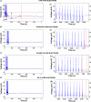
Stimulation artifacts on electrodes produced by a pulse train of ten 10-μA, 800-μs pulses on the same electrode. (A–D) Stimulation artifacts on one each of the three types of plated and the unplated electrodes. (a–d) Zoomed in recordings of the high frequency part of the stimulation artifacts of the respective images on the left (shown with black bars). The dotted red lines show the amplitude and duration of the stimulation artifacts. Amplitude of the stimulation artifact was measured as the difference between the local maxima and local minima following the last pulse delivered. Duration was measured as the time between the last pulse delivered and the time for the voltage to return to 1% of the baseline voltage. The pulses are clipped at 18 mV due to the limitations of our recording system.
Figure 8
Figure 8
(A) Amplitude of the stimulation artifact on the three types of plated and unplated electrodes after ten 10-μs pulses are delivered. Mean ± standard error values on the four electrodes of each type of plating are shown graphically. Values in parentheses show the mean.**p < 0.005 compared to unplated electrodes; #p < 0.27 compared to pulsed plated and DC plated electrodes. (B) Duration of the stimulation artifacts with mean in parentheses and error bars showing standard error.**p < 0.01 compared to unplated electrodes; #p < 0.07 compared to pulsed plated and sonicoplated electrodes.
Figure 9
Figure 9
Thermal noise and EMI together contribute less than 10% of the total noise in an in vivo recording (A) A 17 min recording from a rat on an unplated electrode showing the cessation of neural activity after an injection of euthasol. (B) (L–R) recording on an unplated, sonicoplated, pulsed plated and DC plated electrode in a euthanized rat. Mean RMS noise levels on the three types of plated and unplated electrodes are shown below the respective plots. No significant difference (0.3 < p < 0.6) is seen in the noise levels on the three types of plated and unplated electrodes.

References

    1. Arsiero M., Luscher H. R., Giugliano M. (2007). Real-time closed-loop electrophysiology: towards new frontiers in in vitro investigations in the neurosciences. Arch. Ital. Biol. 145, 193–209 - PubMed
    1. Branner A., Stein R. B., Normann R. A. (2001). Selective stimulation of cat sciatic nerve using an array of varying-length microelectrodes. J. Neurophysiol. 85, 1585–1594 - PubMed
    1. Buzsaki G. (2004). Large-scale recording of neuronal ensembles. Nat. Neurosci. 7, 446–45110.1038/nn1233 - DOI - PubMed
    1. Cogan S. F. (2008). Neural stimulation and recording electrodes. Annu. Rev. Biomed. Eng. 10, 275–30910.1146/annurev.bioeng.10.061807.160518 - DOI - PubMed
    1. Deadwyler S. A., Hampson R. E. (2004). Differential but complementary mnemonic functions of the hippocampus and subiculum. Neuron 42, 465–47610.1016/S0896-6273(04)00195-3 - DOI - PubMed

LinkOut - more resources