. 2011 Jan;28(1):41-57.
doi: 10.1007/s11095-010-0169-8. Epub 2010 May 19.

Design, optimization and characterisation of polymeric microneedle arrays prepared by a novel laser-based micromoulding technique

Affiliations

Design, optimization and characterisation of polymeric microneedle arrays prepared by a novel laser-based micromoulding technique

Ryan F Donnelly et al. Pharm Res. 2011 Jan.

Abstract

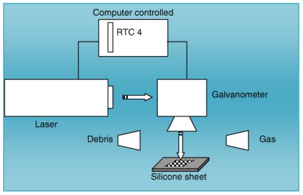
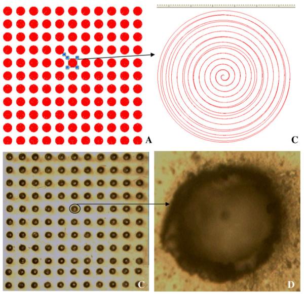
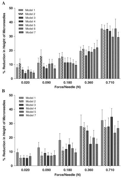
Purpose: Design and evaluation of a novel laser-based method for micromoulding of microneedle arrays from polymeric materials under ambient conditions. The aim of this study was to optimise polymeric composition and assess the performance of microneedle devices that possess different geometries.

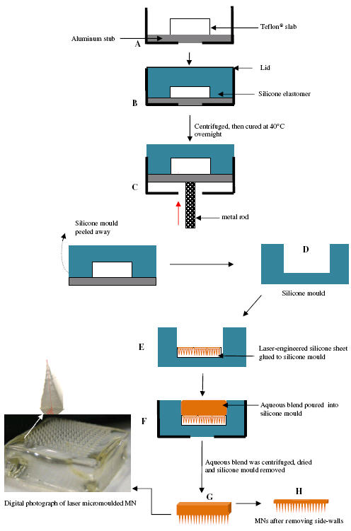
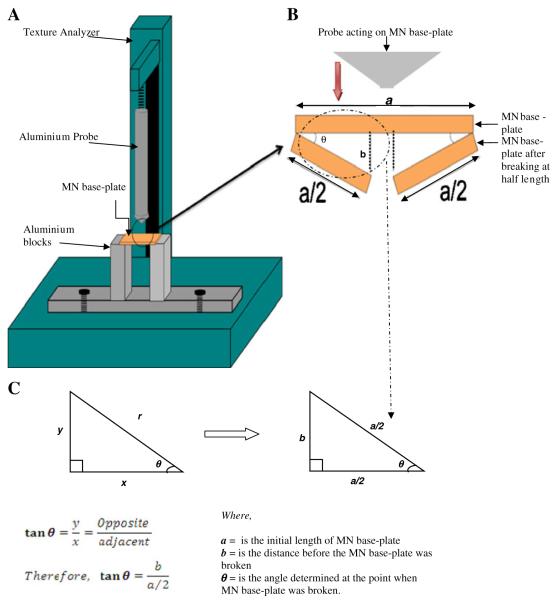
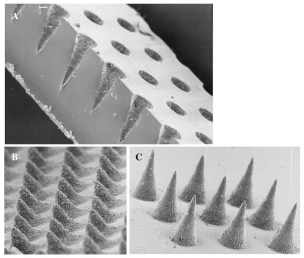
Methods: A range of microneedle geometries was engineered into silicone micromoulds, and their physicochemical features were subsequently characterised.

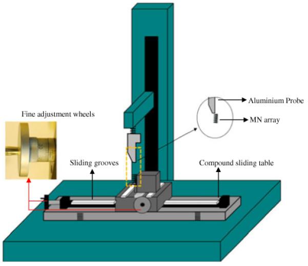
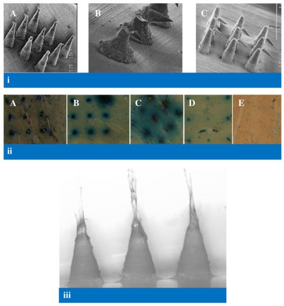
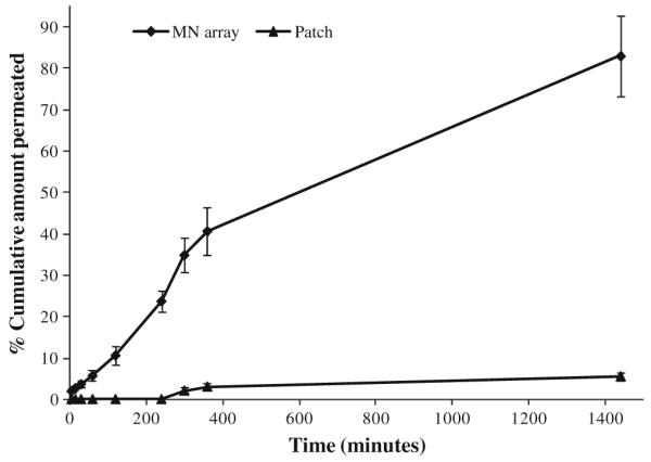
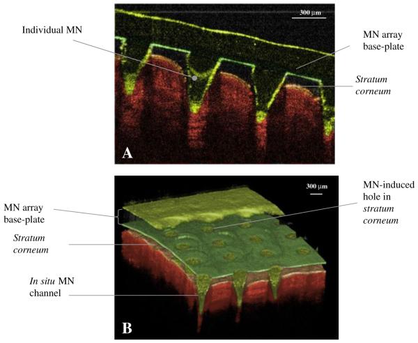
Results: Microneedles micromoulded from 20% w/w aqueous blends of the mucoadhesive copolymer Gantrez® AN-139 were surprisingly found to possess superior physical strength than those produced from commonly used pharma polymers. Gantrez® AN-139 microneedles, 600 μm and 900 μm in height, penetrated neonatal porcine skin with low application forces (>0.03 N per microneedle). When theophylline was loaded into 600 μm microneedles, 83% of the incorporated drug was delivered across neonatal porcine skin over 24 h. Optical coherence tomography (OCT) showed that drug-free 600 μm Gantrez® AN-139 microneedles punctured the stratum corneum barrier of human skin in vivo and extended approximately 460 µm into the skin. However, the entirety of the microneedle lengths was not inserted.

Conclusion: In this study, we have shown that a novel laser engineering method can be used in micromoulding of polymeric microneedle arrays. We are currently carrying out an extensive OCT-informed study investigating the influence of microneedle array geometry on skin penetration depth, with a view to enhanced transdermal drug delivery from optimised laser-engineered Gantrez® AN-139 microneedles.


Figures

Fig. 1
Fig. 1
Illustration of setup of the laser engineering process.
Fig. 2
Fig. 2
Diagrammatic representation of the steps involved in preparation of laser-engineered MN arrays. A Teflon® slab is attached to an aluminium stub using cyanoacrylate glue (A). Silicone is added to the mould and centrifuged at 3,500 rpm for 15 min (B). After curing overnight, the contents of the aluminium container are removed by pressing a metal rod against the aluminium stub (C). Silicone mould is carefully peeled away from the aluminium stub (D). A laser-engineered silicone sheet is attached to the bottom of the silicone mould using cyanoacrylate adhesive (E). Aqueous polymer gel is transferred to the silicone mould (F). The mould is centrifuged, and upon hardening, the silicone mould is carefully peeled away from the MN array (G). Side-walls of MN arrays were cut-off by means of a hot scalpel blade (H).
Fig. 3
Fig. 3
Diagrammatic representation of a microneedle array and its geometrical parameters: (a) height of MNs in array (b) interspacing of MN tips (c) interspacing of MN bases (d) width of MN at base.
Fig. 4
Fig. 4
Illustration of (A) the Texture Analyzer set-up; (B) the method employed in measuring the degree of flexibility of MN base-plates and (C) the equation used to determine the degree of flexibility of MN base-plates.
Fig. 5
Fig. 5
Illustration of the Texture Analyzer set-up for determination of the bending fracture forces of MN arrays.
Fig. 6
Fig. 6
A MN array (11×11) pattern drawn on the system for laser engineering of holes into silicone sheets. B Strategic image of a single hole. C Digital microscope image of laser-engineered silicone micromould (11×11) on 1.0 mm thick silicone sheet. (D) Digital microscope image of a single hole.
Fig. 7
Fig. 7
A SEM of the cross-section of a silicone micromould after laser engineering, revealing cone-shaped holes. B MN arrays prepared from aqueous blends containing 20% w/w Gantrez® AN 139 with 50 μm height showing roughened outer surface. C MN arrays prepared from aqueous blends containing 20% w/w Gantrez® AN 139 with 300 μm height showing optimised surface characteristics.
Fig. 8
Fig. 8
Light microscope images of polymeric microneedles prepared from aqueous blends containing Carbopol® 971-P NF, alginic acid, poly(vinyl) alcohol and Gantrez® AN-139 before, (A, B, C and G respectively), and after (D, E, F and H, respectively) the application of a compression force.
Fig. 9
Fig. 9
A Percentage reduction in height of MN arrays prepared from aqueous blends containing 20% w/w Gantrez® AN 139 as a function of compression force applied. Means (±SD), n>20. B Percentage reduction in height of MN arrays prepared from aqueous blends containing 20% w/w Gantrez® AN 139 as a function of insertion forces applied. Means (± SD), n>20.
Fig. 10
Fig. 10
(i) Scanning electron micrographs of model 7 MN following application of a compression force of 0.02 N per needle (A), model 6 MN following application of a force of approximately 0.17 N perpendicular to the MN shaft (B), model 1 MN following application of a force of approximately 0.08 N perpendicular to the MN shaft (C) (ii) Illustrative digital images of holes created in neonatal porcine skin using various insertion forces for Model 1 MN arrays. A: 0.44 N per needle, B: 0.11 N per needle, C: 0.03 N per needle, D: 0.01 N per needle, E: 0.0056 N per needle. (iii) Illustrative digital image of Gantrez® AN-139 MN arrays (model 3) showing slight elongation in MN tips (due to initiation of dissolution in interstitial tissue fluid) following insertion into neonatal porcine skin for 30 s.
Fig. 11
Fig. 11
Comparative permeation profiles of theophylline across neonatal porcine skin when released from a Gantrez® AN-139 patch and a Gantrez® AN-139 MN array containing the same drug loading. Means (± SD), n>3.
Fig. 12
Fig. 12
OCT images showing MN (height 600 μm, width at base 300 μm, spacing 300 μm) inserted into human skin in vivo in 2D (A) and 3D (B).

Similar articles

Cited by

References

    1. Henry S, McAllister DV, Allen MG, Prausnitz MR. Microfabricated microneedles: a novel approach to transdermal drug delivery. J Pharm Sci. 1998;87:922–5. - PubMed
    1. Prausnitz MR. Microneedles for transdermal drug delivery. Adv Drug Deliv Rev. 2004;56:581–7. - PubMed
    1. Davis SP, Martanto W, Allen MG, Prausnitz MR. Hollow metal microneedles for insulin delivery to diabetic rats. IEEE Trans Biomed Eng. 2005;52:909–15. - PubMed
    1. Moon SJ, Lee SS, Lee HS, Kwon TH. Fabrication of microneedle array using LIGA and hot embossing process. Microsyst Technol Micro Nanosyst Informat Storage Proc Syst. 2005;11:311–8.
    1. Park JH, Allen MG, Prausnitz MR. Biodegradable polymer microneedles: fabrication, mechanics and transdermal drug delivery. J Control Release. 2005;104:51–66. - PubMed

Publication types

MeSH terms