Review
. 2010 Oct 6;7 Suppl 5(Suppl 5):S581-613.
doi: 10.1098/rsif.2010.0156.focus. Epub 2010 May 26.

Electrophoretic deposition of biomaterials

Affiliations
Review

Electrophoretic deposition of biomaterials

A R Boccaccini et al. J R Soc Interface. .

Abstract

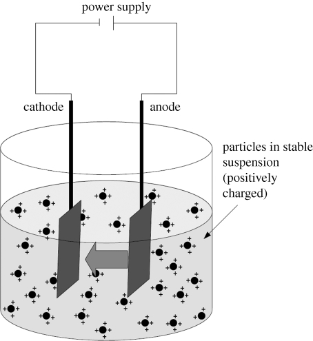
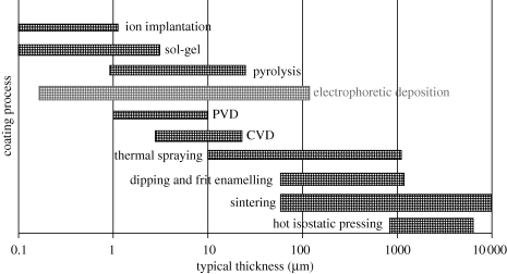
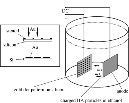
Electrophoretic deposition (EPD) is attracting increasing attention as an effective technique for the processing of biomaterials, specifically bioactive coatings and biomedical nanostructures. The well-known advantages of EPD for the production of a wide range of microstructures and nanostructures as well as unique and complex material combinations are being exploited, starting from well-dispersed suspensions of biomaterials in particulate form (microsized and nanoscale particles, nanotubes, nanoplatelets). EPD of biological entities such as enzymes, bacteria and cells is also being investigated. The review presents a comprehensive summary and discussion of relevant recent work on EPD describing the specific application of the technique in the processing of several biomaterials, focusing on (i) conventional bioactive (inorganic) coatings, e.g. hydroxyapatite or bioactive glass coatings on orthopaedic implants, and (ii) biomedical nanostructures, including biopolymer-ceramic nanocomposites, carbon nanotube coatings, tissue engineering scaffolds, deposition of proteins and other biological entities for sensors and advanced functional coatings. It is the intention to inform the reader on how EPD has become an important tool in advanced biomaterials processing, as a convenient alternative to conventional methods, and to present the potential of the technique to manipulate and control the deposition of a range of nanomaterials of interest in the biomedical and biotechnology fields.


Figures

Figure 1.
Figure 1.
Electrophoretic deposition (EPD) cell showing positively charged particles in suspension migrating towards the negative electrode.
Figure 2.
Figure 2.
Typical thickness of coatings obtained by different process methods, showing the versatility of EPD in that it can produce a wide range of thicknesses of relevance for orthopaedic applications (Sridhar et al. 2002).
Figure 3.
Figure 3.
Schematic of the EPD set-up used by Wang & Hu (2003) to develop patterned HA deposits on Si and Ti substrates indicating also the steps followed to prepare the Au-patterned cathode.
Figure 4.
Figure 4.
Scanning electron microscope (SEM) images of homogeneous Bioglass coatings obtained on stainless steel substrates by EPD from aqueous suspensions containing 20 wt% Bioglass particles at voltages of 5 V and deposition time of 5 min (Krause et al. 2006): (a) top surface and (b) cross section. (Reproduced with permission of Elsevier). Scale bars, (a) 100 µm; (b) 10 µm.
Figure 5.
Figure 5.
SEM images of PEEK/Bioglass-coated NiTi wires at (a) low and (b) high magnification showing the high uniformity of the coating structure achieved. (EPD parameters: Voltage = 20 V, time = 5 min, PEEK concentration = 6 wt%, Bioglass concentration = 1wt%) (Boccaccini et al. 2006c). Scale bars, (a), (b) 50 µm.
Figure 6.
Figure 6.
Schematic diagram of the experimental set-up used to fabricate complex-shaped functionally graded alumina and zirconia-based femoral ball heads by EPD (Anné et al. 2006).
Figure 7.
Figure 7.
Experimental set-up developed by Lin et al. (2008c) to prepare nacre-like coatings, where a two-step assembly process is applied, involving the intercalation of the polymer phase into the interlayer space of montmorillonite and subsequent EPD on a metallic substrate.
Figure 8.
Figure 8.
SEM images of PS–TiO2 electrophoretic deposits, at different magnifications, (a,b) before and (c) after sintering, demonstrating the successful development of a scaled-structured titania coating for orthopaedic applications (Radice et al. 2008, 2010). (Images are courtesy of Dr S. Radice.)
Figure 9.
Figure 9.
SEM images of cross sections of (a) CHIT–BSA and (b) alginate–BSA composite films confirming the electrophoretic formation of relatively uniform films of controlled thickness (Ma & Zhitomirsky 2010; Sun & Zhitomirsky 2010). (Reproduced with permission of Maney Publishing and the Editors of Surface Engineering). Scale bars, (a) 3 µm; (b) 1 µm.
Figure 10.
Figure 10.
Schematic of the process for anchoring HA nanoparticles (positively charged) onto functionalized CNTs (negatively charged): (a) as received CNT, (b) functionalized CNT and (c) attachment of nano-HA particles onto the modified CNT surface (Boccaccini et al. 2010). (Reproduced with permission of Elsevier.)
Figure 11.
Figure 11.
TEM micrograph showing the interaction between TiO2 nanoparticles and CNTs in aqueous suspensions at pH <5 (Singh et al. 2006).
Figure 12.
Figure 12.
Different approaches to fabricate CNT/ceramic nanocomposites by EPD (Boccaccini et al. 2010): (a) schematic diagram showing sequential deposition of CNTs and nanoparticles form layered heterostructures and electrophoretic codeposition; (b) schematic diagram showing different alternatives to produce CNT composites by electrophoretic codeposition: (i) self-assembly of nanoparticles on individual CNTs, (ii) heterocoagulation of CNTs onto individual (larger) particles, and (iii) simultaneous deposition of CNTs and ceramic particles with the same charge polarity in suspension. (Reproduced with permission of Elsevier.) Plain thin curves, CNTs; open circles, ceramic or metallic particles.
Figure 13.
Figure 13.
SEM images showing the typical microstructure of a CNT-coated Bioglass-based scaffold, obtained by EPD (2.8 V, 10 min) at different magnifications (Meng et al. 2009). Scale bars, (a) 100 µm; (b) 1 µm. (Images courtesy of Dr Decheng Meng.)
Figure 14.
Figure 14.
SEM images showing (a) inclusion bodies electrophoretically deposited on steel cathode from suspensions at IEP of E. coli bacteria (3 min of EPD at 7.5 V cm−1) and (b) deposition of E. coli on the anode after the pH was set to the IEP of the inclusion bodies (Novak et al. 2009). Scale bars, (a,b) 10 µm. (Reproduced with permission of Elsevier.)
Figure 15.
Figure 15.
Schematic diagram showing different conditions at the surface of colloidal particles and cells, as suggested by Akagi & Ichiki (2008).

Similar articles

Cited by

References

    1. Affoune A. M., Prasad B. L. V., Sato H., Enoki T. 2001. Electrophoretic deposition of nanosized diamond particles. Langmuir 17, 547–551. (10.1021/la001317f) - DOI
    1. Ahmad Z., Nangrejo M., Edirisinghe M., Stride E., Colombo P., Zhang H. B. 2009. Engineering a material for biomedical applications with electric field assisted processing. Appl. Phys. A. Mater. Sci. Process. 97, 31–37.
    1. Akagi T., Ichiki T. 2008. Cell electrophoresis on a chip: what can we know from the changes in electrophoretic mobility? Anal. Bioanal. Chem. 391, 2433–2441. (10.1007/s00216-008-2203-9) - DOI - PubMed
    1. Akasaka T., Watari F., Sato Y., Tohji K. 2006. Apatite formation on carbon nanotubes. Mater. Sci. Eng. C 26, 675–678. (10.1016/j.msec.2005.03.009) - DOI
    1. Albayrak O., El-Atwani O., Altintas S. 2008. Hydroxyapatite coating on titanium substrate by electrophoretic deposition method: effects of titanium dioxide inner layer on adhesion strength and hydroxyapatite decomposition. Surf. Coat. Technol. 202, 2482–2487. (10.1016/j.surfcoat.2007.09.031) - DOI

LinkOut - more resources