. 2010 Jun 1;6(6):433-437.
doi: 10.1038/nphys1637.

Integrated Elastomeric Components for Autonomous Regulation of Sequential and Oscillatory Flow Switching in Microfluidic Devices

Affiliations

Integrated Elastomeric Components for Autonomous Regulation of Sequential and Oscillatory Flow Switching in Microfluidic Devices

Bobak Mosadegh et al. Nat Phys. .

Abstract

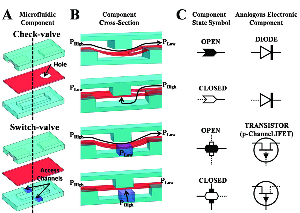
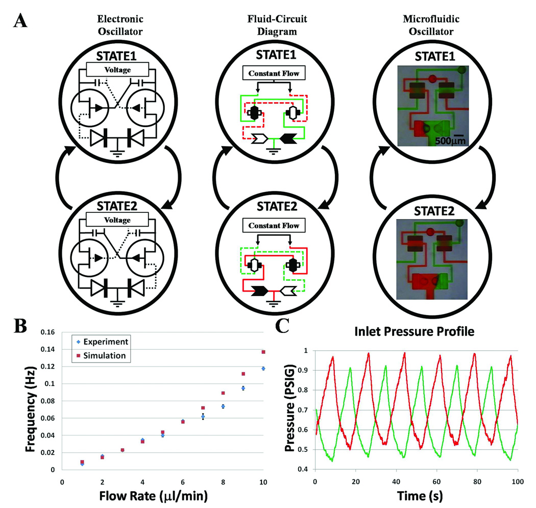
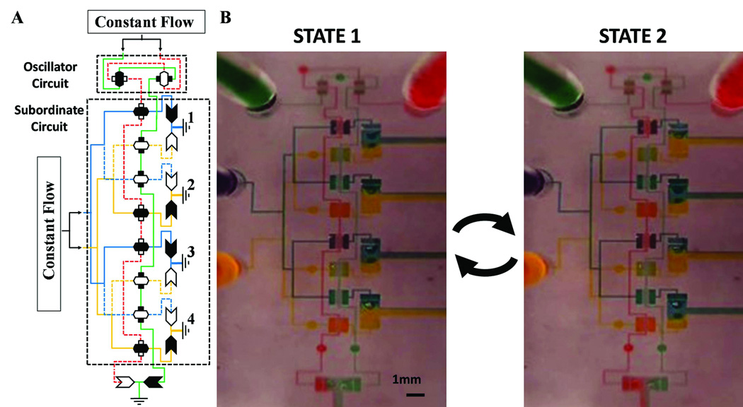
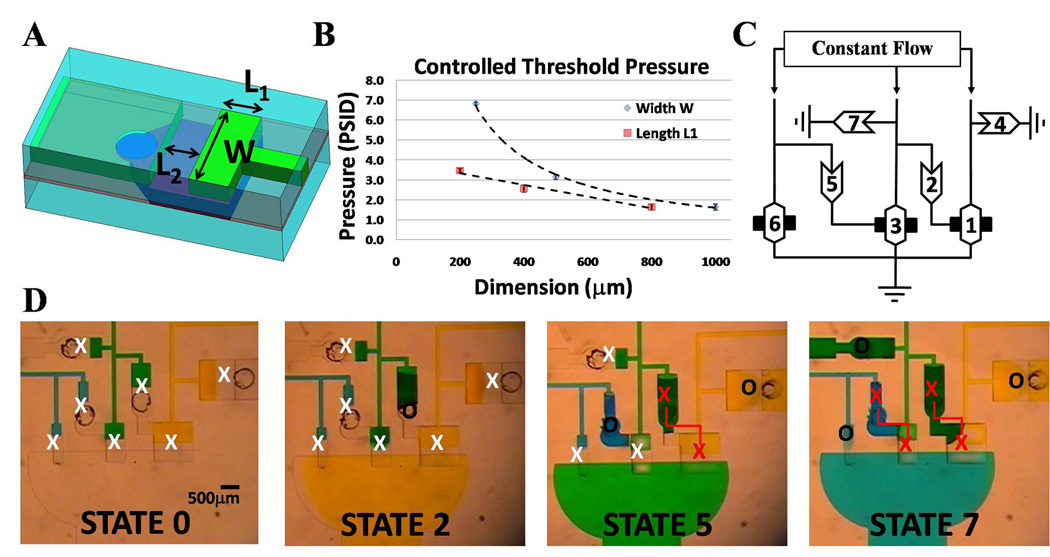
A critical need for enhancing usability and capabilities of microfluidic technologies is the development of standardized, scalable, and versatile control systems1,2. Electronically controlled valves and pumps typically used for dynamic flow regulation, although useful, can limit convenience, scalability, and robustness3-5. This shortcoming has motivated development of device-embedded non-electrical flow-control systems. Existing approaches to regulate operation timing on-chip, however, still require external signals such as timed generation of fluid flow, bubbles, liquid plugs or droplets, or an alteration of chemical compositions or temperature6-16. Here, we describe a strategy to provide device-embedded flow switching and clocking functions. Physical gaps and cavities interconnected by holes are fabricated into a three-layer elastomer structure to form networks of fluidic gates that can spontaneously generate cascading and oscillatory flow output using only a constant flow of Newtonian fluids as the device input. The resulting microfluidic substrate architecture is simple, scalable, and should be applicable to various materials. This flow-powered fluidic gating scheme brings the autonomous signal processing ability of microelectronic circuits to microfluidics where there is the added diversity in current information of having distinct chemical or particulate species and richness in current operation of having chemical reactions and physical interactions.


Figures

Fig. 1
Fig. 1. Elastomeric components for autonomously controlled microfluidic devices
(A) A three-layer composite of the check-valve and switch-valve. (B) Cross-section schematic of check-valve and switch-valve in both open and closed state based on differential pressure. (C) Corresponding component state symbol of the check-valve and switch-valve. Conducting current/flow is shown as solid lines and non-conducting current/flow is shown as dotted lines. (D) The diode and p-channel JFET transistor are shown as analogous electronic components to the check-valve and switch-valve, respectively.
Fig. 2
Fig. 2. Interactive elastomeric components for oscillatory switching
(A) Comparison between microfluidic oscillator and electronic oscillator. The two states of a microfluidic oscillator automatically produce an alternating output flow between two distinct solutions being simultaneously infused at a constant rate. (B) Graph of both the simulated and experimental data for the oscillators switching frequency for various flow rates within its operating range. Error bars represent the standard deviations from three measurements taken at each flow rate. (C) Graph of pressure oscillations at solution inlets for an infusion rate of 10µl/min.
Fig. 3
Fig. 3. Fluidic oscillator controls flow in subordinate fluid-circuit
(A) Fluid-circuit diagram for state 1 of a microfluidic oscillator providing input signals (red and green solutions) to a subordinate fluid-circuit which distributes flow of two solutions (yellow and blue) to 4 outlets. (B) Actual images of both states for the fluid-circuit with an infusion rate of 100µl/min which oscillates at 1 Hz.
Fig. 4
Fig. 4. Automated Fluid Circuits for Cascading Operations
(A) Geometric parameters that dictate component opening threshold pressure for check-valve and diode. (B) Graph showing linear and non-linear dependence of check-valve’s geometries for varying L1 and W dimensions (while other dimension is held constant), respectively. Error bars represent the standard deviations from measurements taken from three separate devices. (C) Fluid-circuit diagram of a device that sequentially switches between three solutions being infused simultaneously at a constant flow rate. This circuit is a simple finite state machine that performs a predefined sequence of operations. Numbers in components show order of opening. (D) Actual images of four of the seven states with “X” and “O” representing closed and opened valves, respectively. Red “X”s connected by a line designate check-valve and switch-valve modules that lock in pressure to maintain the two linked valves closed once a threshold is surpassed.

References

    1. Whitesides GM. The origins and the future of microfluidics. Nature. 2006;442:368–373. - PubMed
    1. Pennathur S. Flow control in microfluidics: are the workhorse flows adequate? Lab Chip. 2008;8:383–387. - PubMed
    1. Unger MA, Chou HP, Thorsen T, Scherer A, Quake SR. Monolithic microfabricated valves and pumps by multilayer soft lithography. Science. 2000;288:113–116. - PubMed
    1. Gu W, Zhu X, Futai N, Cho BS, Takayama S. Computerized microfluidic cell culture using elastomeric channels and Braille displays. Proc. Natl Acad. Sci. USA. 2004;101:15861–15866. - PMC - PubMed
    1. Xie J, Shih J, Lin Q, Yang B, Tai YC. Surface micromachined electrostatically actuated micro peristaltic pump. Lab Chip. 2004;4:495–501. - PubMed