. 2010 Aug 20;285(34):26350-7.
doi: 10.1074/jbc.M110.123117. Epub 2010 Jun 15.

Actin cross-link assembly and disassembly mechanics for alpha-Actinin and fascin

Affiliations

Actin cross-link assembly and disassembly mechanics for alpha-Actinin and fascin

David S Courson et al. J Biol Chem. .

Abstract

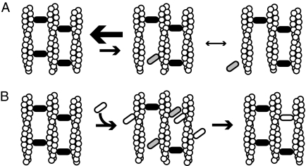
Self-assembly of complex structures is commonplace in biology but often poorly understood. In the case of the actin cytoskeleton, a great deal is known about the components that include higher order structures, such as lamellar meshes, filopodial bundles, and stress fibers. Each of these cytoskeletal structures contains actin filaments and cross-linking proteins, but the role of cross-linking proteins in the initial steps of structure formation has not been clearly elucidated. We employ an optical trapping assay to investigate the behaviors of two actin cross-linking proteins, fascin and alpha-actinin, during the first steps of structure assembly. Here, we show that these proteins have distinct binding characteristics that cause them to recognize and cross-link filaments that are arranged with specific geometries. alpha-Actinin is a promiscuous cross-linker, linking filaments over all angles. It retains this flexibility after cross-links are formed, maintaining a connection even when the link is rotated. Conversely, fascin is extremely selective, only cross-linking filaments in a parallel orientation. Surprisingly, bundles formed by either protein are extremely stable, persisting for over 0.5 h in a continuous wash. However, using fluorescence recovery after photobleaching and fluorescence decay experiments, we find that the stable fascin population can be rapidly competed away by free fascin. We present a simple avidity model for this cross-link dissociation behavior. Together, these results place constraints on how cytoskeletal structures assemble, organize, and disassemble in vivo.


Figures

FIGURE 1.
FIGURE 1.
Optically trapped filaments are used to build specific actin architectures for analysis of cross-linker angular dependence of binding. A, α-actinin is active as an anti-parallel homodimer. Each monomer contains an actin binding domain (ABD) composed of two calponin homology (CH) domains. A series of four spectrin repeats (S1–4) make up the dimerization domain. Each monomer also contains two EF hand domains that are responsible for modulating protein behavior based on calcium signaling (24). Smooth muscle α-actinin, the form used in this study, is calcium-insensitive. B, fascin is functional as a monomer made of a tight cluster of four fascin domains (F). C, flow chamber with four lanes is used to add reagents in isolation. Beads are added in channel 1, actin filaments in channel 2, and cross-linking proteins in channel 4. Channel 3, which contains only buffer, is used to arrange structures without accidental addition of other components and serves as a barrier between the actin and cross-linker channels to prevent diffusional mixing and unintended aggregation. The black arrows indicate the direction of flow. D, to examine binding behavior of proteins based on actin orientation, two actin filaments were trapped between four 1-μm polystyrene beads. Filaments were crossed and rotated (dashed arrow) until a desired angle was achieved. White arrowheads indicate filament polarity. × indicates optical traps. E, once the desired angle was achieved, one filament was scanned (dashed arrows) over the other, allowing for the exploration of a large number of potential binding sites. Binding events were recorded when the scanned filament stuck at one point on the stationary filament during the scan, and a deformation of the scanned filament was observed. F, parallel and anti-parallel arrangements were also tested. A single filament was stretched out perpendicular to the fluid flow, and a second filament was allowed to touch that filament tangentially. If no interaction was observed, one of the filaments was rotated 180°, and the experiment was repeated. G, to assess if the proteins would bind anti-parallel filaments, a single filament was wrapped around a bead, and the ends were allowed to interact. Arrows indicate the polarity of the neighboring section of filament. H, addition of a second filament to the wrapped filament assay produces areas of parallel and anti-parallel alignment. For proteins that are selective for parallel versus anti-parallel arrangements, the combination of the assays in G and H clearly shows the preference. I, single bead assays were also performed where two filaments of unknown polarity were attached to a single bead. If they always link, then there is no polarity preference. If they never link, then a given protein cannot bind aligned filaments. If they bind 50% of trails, it implies that there is a selection for one orientation, the orientation of which a wrapped bead experiment as described in section G can determine.
FIGURE 2.
FIGURE 2.
α-Actinin is a flexible cross-linker that cross-links actin in all orientations examined. A–C, gallery shows the formation of a single cross-link by α-actinin at a 90° cross of two actin filaments on three beads (supplemental Movie S1). d--H, α-actinin bundles aligned filaments. The filament marked in red is strung between the two beads and wraps around the top bead. The blue filament is strung between the two beads. All three filament segments bind into a tight bundle. This arrangement necessitates the formation of anti-parallel cross-links and could include parallel cross-links as well (supplemental Movie S2). I–P, α-actinin cross-link is stable, remaining bound while the link is rotated and pulled in various directions. Gallery shows a 48-s range. This link was observed for more than 3 min before the complex fell out of the optical traps (supplemental Movie S3). Scale bar in all figures equals 1 μm.
FIGURE 3.
FIGURE 3.
Fascin only cross-links actin when filaments are arranged in a parallel orientation. A–C, fascin does not bind in a crossed orientation near 90°. The free end of a filament with only one end bound to a bead was allowed to freely scan over an anchored filament. No binding events were observed. Because of the bend in the filament with both ends anchored to beads, all crossing was near 90° (±10°). Approximately 2.5 μm length of the anchored filament was probed by the free filament end (∼900 potential binding sites). At 1 μm fascin concentration, ∼50% of the available fascin-binding sites should be filled, so the scanning filament should have found a viable binding site if the orientation of the filaments was conducive to binding. Dotted lines indicate the range over which the free filament scanned (supplemental Movie S4). d–I, a pair of crossed filaments was arranged and scanned. No binding events were observed. This pair of filaments was tested over a range of ∼100° and scanned over a 1.5 μm distance at ∼15° increments (supplemental Movie S5). J–N, fascin does not bind in an anti-parallel orientation as shown by this filament wrapped around a nonfluorescent bead. Filament ends diffused together but never remained coupled (supplemental Movie S6). O–S, one filament (red) wraps around a bead that has a second filament (blue) attached. One side of the red filament bundles with the blue filament, but the other does not. This behavior is explained by polarity selection. Coupled with the results from J–N, we can determine that fascin will bind parallel but not anti-parallel filaments (supplemental Movie S7).
FIGURE 4.
FIGURE 4.
Bundles do not dissociate even over long time scales. A–F, one long filament was attached in the middle to a bead, and the ends were allowed to form a bundle in the presence of 0.1 μm α-actinin. After bundle formation, the bundle was moved into the buffer lane, and all other flow lanes were turned off. The bundle was observed periodically over 40 min. The filaments were never observed to separate (supplemental Movie S8) This experiment was replicated six times with the same results, using bundles derived from one to three filaments (two to three lengths of filaments incorporated into the bundle). G–L, two filaments were attached to a bead, and the same experiment was performed using 0.1 μm fascin. As with α-actinin, the fascin bundles were extremely stable, showing no dissociation over 40-min observations. This experiment was replicated six times using two and three filaments in the bundle (supplemental Movie S9). Additional material on this experiment is found in supplemental Figs. S3 and S4 and supplemental Movies S10–S13.
FIGURE 5.
FIGURE 5.
Fluorescence decay and FRAP of labeled fascin in bundles shows the fascin population is stable unless a competitor is added. A–D, bundle of dark actin held together by fluorescent atto-647-fascin (labeled on exposed cysteines using maleimide chemistry, measured 0.95 dyes/fascin) is bleached and then observed in a series of movies over 400 s. Before bleaching, the flow cell was rinsed with buffer to remove free fascin from solution. The boundary between the bleached and unbleached regions of the bundle remained sharp and the signal from the unbleached portion of the bundle remained nearly constant. The white ring indicates the zone of bleaching. Low observational laser power was used to facilitate the long acquisition time by minimizing photobleaching. E, fascin in the bundle is stable in the absence of cross-linker in solution. The graph shows the fluorescence decay profile of the four highlighted regions from D, recorded during the final movie of this observation. The fluorescence of the bundle (red) remains stable and higher than the other three regions. The green curve is background in the bleached zone; orange is the background outside of the bleached zone, and blue is the bundle in the bleached zone. F, fascin in bundles can be competed away. A series of buffer wash experiments using bundles similar to those in A–D were performed. In all cases the bundles had been rinsed with buffer to remove free fascin from solution before data were recorded. All data points are background subtracted and then normalized so that a value of 1 corresponded to the average value of the first 25 data points after the wash was initiated. When the bundles were washed with buffer only (red), a slow decay (0.019 ± 0.003 s−1, S.E.) was seen in the fluorescent signal. This corresponds to the photobleaching rate at the laser powers used in these experiments. When 3 μm unlabeled fascin (black) was washed in a double exponential decay was observed. The faster rate corresponds to fascin being displaced from the bundle (0.10 ± 0.007 s−1, S.E.). This value closely matches that of Aratyn et al. (38), who reported a decay rate of 0.12 s−1. The slower rate (0.023 ± 0.002 s−1, S.E.) corresponds to photobleaching. When 3 μm unlabeled α-actinin was washed in a rapid single exponential decay was observed (0.254 ± 0.004 s−1, S.E.). This is even more rapid than the decay observed with the addition of fascin. This shows that the presence of a competitive agent causes rapid cross-linker turnover. G, fascin replacement is uniform and complete across the entire bundle. With no fascin in solution, a region of a bundle made with fluorescent fascin was bleached. Blue indicates the area of the bundle that was bleached, and red indicates the area that was not bleached. After bleaching, a significant difference in signal between the two curves is observed. Next, 3 μm fluorescent fascin was washed into the chamber (around the 20-s mark, where signal rises to saturation). It was allowed to incubate for 30 s and then was washed out with buffer. The wash is completed, and the signal drops to resolvable levels after approximately an additional 20 s. At this point, the bundle inside and outside the bleach zone have the same fluorescence. This confirms that free fascin can incorporate completely and evenly into the bundle.
FIGURE 6.
FIGURE 6.
Models of bundle formation and dynamics. A, bundles are stable in the absence of competitive agents. Cross-linking proteins that are bound to two filaments (black ovals) stabilize filament bundles. These proteins can toggle to a state (gray ovals) where they are only bound to a single filament. Because the actin site is restrained, the single bound cross-linker can readily rebind the second filament. This rebinding rate is faster than the dissociation rate in the single bound state, yielding bundles that are very stable. B, when a competitive agent (white oval) is added to a stable bundle it can occupy actin sites near single bound cross-linkers, preventing their rebinding. This leads to dissociation of the endogenous cross-linker and either replacement with the exogenous agent (shown) or dissociation of both factors (not shown). If cross-linking protein is abundant in solution, there is a constant exchange of proteins in the bundle as shown by previous FRAP experiments.

Similar articles

Cited by

References

    1. Otto J. J., Kane R. E., Bryan J. (1979) Cell 17, 285–293 - PubMed
    1. Heggeness M. H., Wang K., Singer S. J. (1977) Proc. Natl. Acad. Sci. U.S.A. 74, 3883–3887 - PMC - PubMed
    1. Kane R. E. (1976) J. Cell Biol. 71, 704–714 - PMC - PubMed
    1. Kane R. E. (1975) J. Cell Biol. 66, 305–315 - PMC - PubMed
    1. Goll D. E., Mommaerts W. F., Reedy M. K., Seraydarian K. (1969) Biochim. Biophys. Acta 175, 174–194 - PubMed

Publication types

LinkOut - more resources