

Numerical investigation of the performance of three hinge designs of bileaflet mechanical heart valves
- PMID: 20571852
- PMCID: PMC2949571
- DOI: 10.1007/s10439-010-0086-3
Numerical investigation of the performance of three hinge designs of bileaflet mechanical heart valves
Abstract
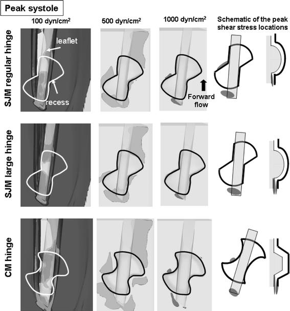
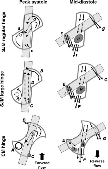
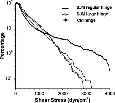
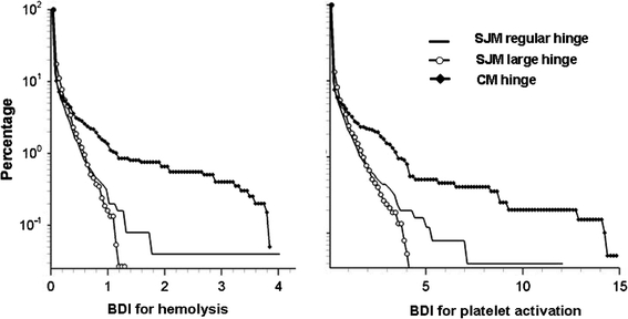
Thromboembolic complications (TECs) of bileaflet mechanical heart valves (BMHVs) are believed to be due to the nonphysiologic mechanical stresses imposed on blood elements by the hinge flows. Relating hinge flow features to design features is, therefore, essential to ultimately design BMHVs with lower TEC rates. This study aims at simulating the pulsatile three-dimensional hinge flows of three BMHVs and estimating the TEC potential associated with each hinge design. Hinge geometries are constructed from micro-computed tomography scans of BMHVs. Simulations are conducted using a Cartesian sharp-interface immersed-boundary methodology combined with a second-order accurate fractional-step method. Leaflet motion and flow boundary conditions are extracted from fluid-structure-interaction simulations of BMHV bulk flow. The numerical results are analyzed using a particle-tracking approach coupled with existing blood damage models. The gap width and, more importantly, the shape of the recess and leaflet are found to impact the flow distribution and TEC potential. Smooth, streamlined surfaces appear to be more favorable than sharp corners or sudden shape transitions. The developed framework will enable pragmatic and cost-efficient preclinical evaluation of BMHV prototypes prior to valve manufacturing. Application to a wide range of hinges with varying design parameters will eventually help in determining the optimal hinge design.
Figures


Similar articles
-
Simulation of the three-dimensional hinge flow fields of a bileaflet mechanical heart valve under aortic conditions.Ann Biomed Eng. 2010 Mar;38(3):841-53. doi: 10.1007/s10439-009-9857-0. Epub 2009 Dec 4. Ann Biomed Eng. 2010. PMID: 19960368 Free PMC article.
-
A numerical investigation of blood damage in the hinge area of aortic bileaflet mechanical heart valves during the leakage phase.Ann Biomed Eng. 2012 Jul;40(7):1468-85. doi: 10.1007/s10439-011-0502-3. Epub 2012 Jan 4. Ann Biomed Eng. 2012. PMID: 22215278
-
Comparison of platelet activation through hinge vs bulk flow in bileaflet mechanical heart valves.J Biomech. 2019 Jan 23;83:280-290. doi: 10.1016/j.jbiomech.2018.12.003. Epub 2018 Dec 11. J Biomech. 2019. PMID: 30579576
-
A review of state-of-the-art numerical methods for simulating flow through mechanical heart valves.Med Biol Eng Comput. 2009 Mar;47(3):245-56. doi: 10.1007/s11517-009-0438-z. Epub 2009 Feb 5. Med Biol Eng Comput. 2009. PMID: 19194734 Free PMC article. Review.
-
Are all bileaflet mechanical valves equal?Curr Opin Cardiol. 2009 Mar;24(2):136-41. doi: 10.1097/HCO.0b013e328324e698. Curr Opin Cardiol. 2009. PMID: 19532099 Review.
Cited by
-
Numerical Modeling of Intraventricular Flow during Diastole after Implantation of BMHV.PLoS One. 2015 May 11;10(5):e0126315. doi: 10.1371/journal.pone.0126315. eCollection 2015. PLoS One. 2015. PMID: 25961285 Free PMC article.
-
Evaluation of shear-induced platelet activation models under constant and dynamic shear stress loading conditions relevant to devices.Ann Biomed Eng. 2013 Jun;41(6):1279-96. doi: 10.1007/s10439-013-0758-x. Epub 2013 Feb 12. Ann Biomed Eng. 2013. PMID: 23400312 Free PMC article.
-
Blood damage through a bileaflet mechanical heart valve: a quantitative computational study using a multiscale suspension flow solver.J Biomech Eng. 2014 Oct;136(10):101009. doi: 10.1115/1.4028105. J Biomech Eng. 2014. PMID: 25070372 Free PMC article.
-
A Novel Attempt to Standardize Results of CFD Simulations Basing on Spatial Configuration of Aortic Stent-Grafts.PLoS One. 2016 Apr 13;11(4):e0153332. doi: 10.1371/journal.pone.0153332. eCollection 2016. PLoS One. 2016. PMID: 27073907 Free PMC article.
-
Fluid-structure interaction simulation of mechanical aortic valves: a narrative review exploring its role in total product life cycle.Front Med Technol. 2024 Jul 1;6:1399729. doi: 10.3389/fmedt.2024.1399729. eCollection 2024. Front Med Technol. 2024. PMID: 39011523 Free PMC article. Review.
References
-
- Dasi LP, Ge L, Simon HA, Sotiropoulos F, Yoganathan AP. Vorticity dynamics of a bileaflet mechanical heart valve in an axisymmetric aorta. Phys. Fluids. 2007;19:067105(1)–067105(17). doi: 10.1063/1.2743261. - DOI
Publication types
MeSH terms
Grants and funding
LinkOut - more resources
Full Text Sources
Miscellaneous
