. 2010 May 28:3:6.
doi: 10.3389/fneng.2010.00006. eCollection 2010.

Seven years of recording from monkey cortex with a chronically implanted multiple microelectrode

Affiliations

Seven years of recording from monkey cortex with a chronically implanted multiple microelectrode

Jürgen Krüger et al. Front Neuroeng. .

Abstract

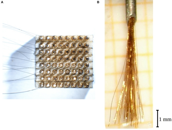
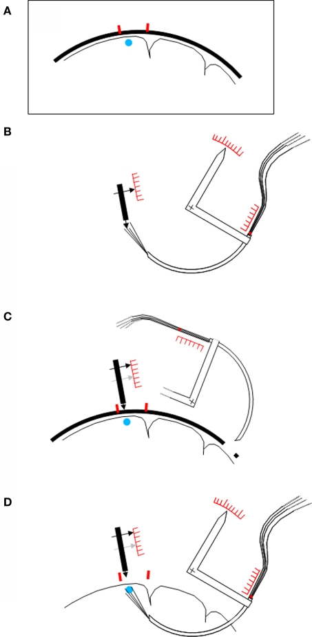
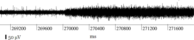
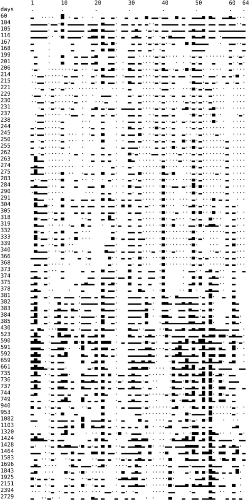
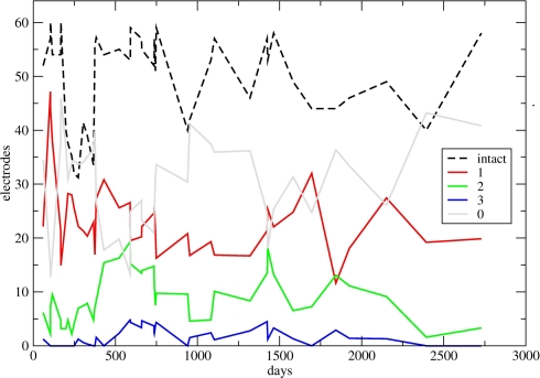
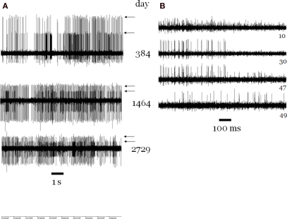
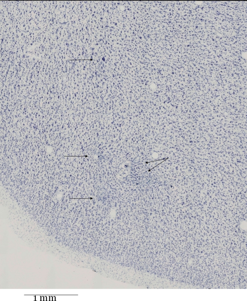
A brush of 64 microwires was chronically implanted in the ventral premotor cortex of a macaque monkey. Contrary to common approaches, the wires were inserted from the white matter side. This approach, by avoiding mechanical pressure on the dura and pia mater during penetration, disturbed only minimally the cortical recording site. With this approach isolated potentials and multiunit activity were recorded for more than 7 years in about one-third of electrodes. The indirect insertion method also provided an excellent stability within each recording session, and in some cases even allowed recording from the same neurons for several years. Histological examination of the implanted brain region shows only a very marginal damage to the recording area. Advantages and problems related to long-term recording are discussed.

Keywords: chronic implant; indirect insertion; monkey; multielectrode; premotor cortex.


Figures

Figure 1
Figure 1
Electrode construction. (A) View of the 64-fold plug from underneath while 16 wires have already been contacted by silver epoxy (leftmost two columns). After curing they will be covered by insulating epoxy and then the next two columns be contacted. The distance between two contacts is 0.9 mm. (B) View of a ready 64-fold electrode brush protruding from the cannula (top).
Figure 2
Figure 2
Schematic procedure of the implantation. (A) Schematic drawing of a magnetic resonance image showing the brain to be investigated, with the target area (blue point) and two small titanium screws (red) in the nearby bone. (B) Adjustment of the device before the implantation. A “skull pointer” (left black arrow) is lowered into the middle of the region of the electrode tips, and its position is noted on a scale. The angular position of the rotating device carrying the cannula (white arrow), and the extent of insertion of the bundle of wires into the hind end of the cannula, are also noted on corresponding scales. (C) The skull pointer is retracted by the bone surface–target point distance, the cannula with the electrodes is rotated away, and the electrodes are retracted into the cannula. Guided by the positions of the screws the pointer tip is then brought in contact with the animal's skull, and a far lateral trepanation (right) is made. (D) The cannula is rotated into the brain, and then the bundle of wires is pushed forward, until the two previously noted positions are reached. An additional feature of the device (not shown in the figure) is that the entire system of pointer and cannula carrier can be rotated around the selected target point. In the case of a disturbing blood vessel encountered at the intended entry point within the trepanation, another entry site can easily be selected without new adjustments.
Figure 3
Figure 3
Record of a channel showing the typical effect of an interruption of the contact within the plug on the head of the animal: the spikes disappear, and the width of the noise level is duplicated.
Figure 4
Figure 4
Temporal development of recording quality. Left column: time (in days) after implantation. Symbols: Dot: technically defect electrode or amplification channel. Blank: technically intact, but no spike recorded. Rectangles of different height: 1, 2, or 3 spike trains recorded, respectively, by each one electrode. On electrode no 2 on days 263 and 275 we could properly discriminate four different spike trains. This is rendered by higher rectangles but the category “four spike separable trains” was not considered henceforth.
Figure 5
Figure 5
Temporal development of recording quality, summated over all electrodes. In some sections of the diagrams, many experiments done within a few days led to a crowding of symbols; in these cases up to six successive counts have been averaged, without loss of the general character of the curves. Black dashed curve: for each day (or up to 6 days), number of technically intact electrodes or channels. Continuous curves: for each day (or up to 6 days), number of electrodes recording 1, 2, 3, and 0 spike trains (red, green, blue, and gray), respectively, normalized to 64 intact electrodes. For the normalization, for each day the corresponding numbers have been multiplied by 64 and divided by the height of the dashed curve. The higher value of technically intact electrodes on the last day is due to a previous cleaning of the plugs, and in addition to a threefold permutation of electrodes and headstage/amplificator channels so that the true recording quality of many more electrodes could be examined.
Figure 6
Figure 6
(A) Sections of recordings from channel 54 separated by more than 6 years, showing two trains of spikes (arrows). From day 384 on, in all recordings with intact channel 54, two trains of well-isolated spikes, with high ongoing discharge rates, were seen. On a few days (not shown) a smaller third spike train appeared. The noise level width is about 50 μV in all cases. (B) Four simultaneous recordings on day 168. The spike trains on channel 30 (number at right) can be seen also to appear on channels 10 and 47. Another train of smaller spikes on channel 47 can be seen also to appear on channel 49 (right side).
Figure 7
Figure 7
Nissl-stained frontal section (thickness 60 μm) through the middle of the “cloud” of electrode tips. The location is the F5 region in the posterior bank of the arcuate sulcus just lateral/below its spur. The four upper arrows point to localized gliosis. The lower arrow points to a lesion near a larger blood vessel filled with detritus. The lesion is more prominent in adjacent sections (not shown) towards the root of the brush of electrodes.

References

    1. Andersen R. A., Musallam S., Pesaran B. (2004). Selecting the signals for a brain-machine interface. Curr. Opin. Neurobiol. 14, 720–72610.1016/j.conb.2004.10.005 - DOI - PubMed
    1. Dalla Volta R., Grammont F., Bruzzo A., Krüger J. (2002). Chronical multielectrode recording applied to monkey ventral premotor cortex. Poster presented at “The Human Brain.” 1st International conference, October 2002, Fondazione IRCCSSanta Lucia, Roma
    1. Donoghue J. P. (2008). Bridging the brain to the world: a perspective on neural interface systems. Neuron 60, 511–52110.1016/j.neuron.2008.10.037 - DOI - PubMed
    1. Fraser G. W., Chase S. M., Whitford A., Schwartz A. B. (2009). Control of a brain–computer interface without spike sorting. J. Neural Eng 6, 055004 (8 pp). - PubMed
    1. Hatsopoulos N. G., Donoghue J. P. (2009). The science of neural interface systems. Annu. Rev. Neurosci. 32, 249–26610.1146/annurev.neuro.051508.135241 - DOI - PMC - PubMed

LinkOut - more resources