

Experimental investigation of cryogenic oscillating heat pipes
- PMID: 20585410
- PMCID: PMC2888510
- DOI: 10.1016/j.ijheatmasstransfer.2009.03.013
Experimental investigation of cryogenic oscillating heat pipes
Abstract
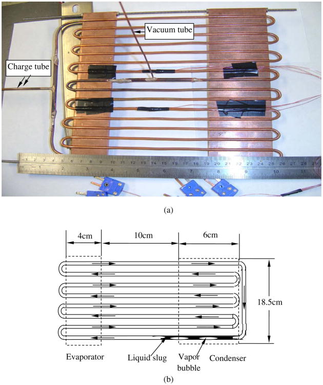
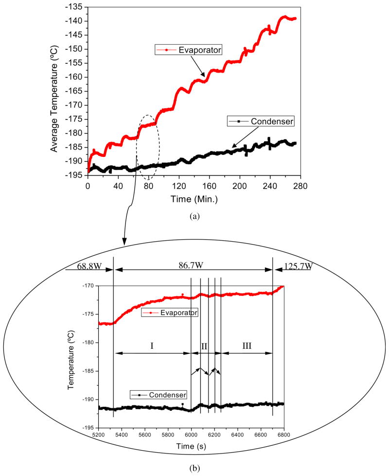
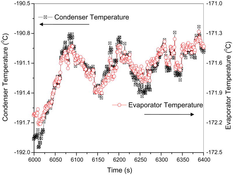
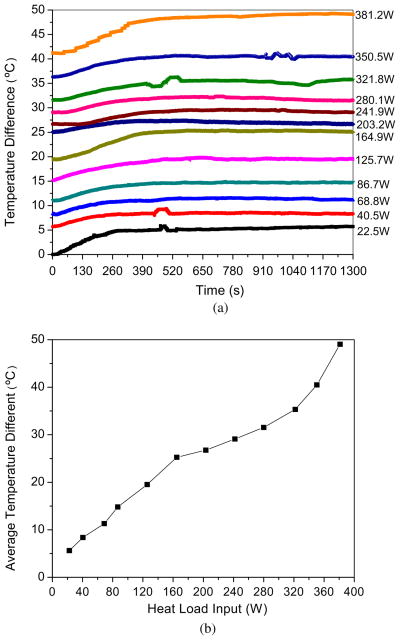
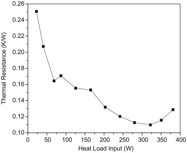
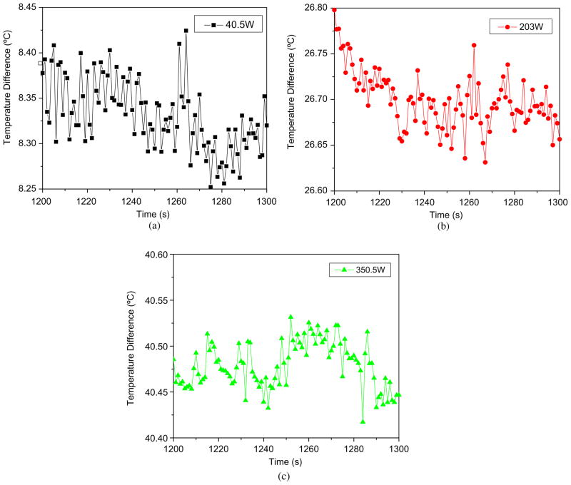
A novel cryogenic heat pipe, oscillating heat pipe (OHP), which consists of an 4 × 18.5 cm evaporator, a 6 × 18.5 cm condenser, and 10 cm length of adiabatic section, has been developed and experimental characterization conducted. Experimental results show that the maximum heat transport capability of the OHP reached 380W with average temperature difference of 49 °C between the evaporator and condenser when the cryogenic OHP was charged with liquid nitrogen at 48% (v/v) and operated in a horizontal direction. The thermal resistance decreased from 0.256 to 0.112 while the heat load increased from 22.5 to 321.8 W. When the OHP was operated at a steady state and an incremental heat load was added to it, the OHP operation changed from a steady state to an unsteady state until a new steady state was reached. This process can be divided into three regions: (I) unsteady state; (II) transient state; and (III) new steady state. In the steady state, the amplitude of temperature change in the evaporator is smaller than that of the condenser while the temperature response keeps the same frequency both in the evaporator and the condenser. The experimental results also showed that the amplitude of temperature difference between the evaporator and the condenser decreased when the heat load increased.
Figures
References
-
- Chandratilleke R, Hatakeyama H, Nakagome H. Development of cryogenic loop heat pipes. Cryogenics. 1998;38(3):263–269.
-
- Jiao AJ, Han X, Critser JK, Ma HB. Numerical investigations of transient heat transfer characteristics and vitrification tendencies in ultra-fast cell freezing processes. Cryobiology. 2006;52(3):386–392. - PubMed
-
- Zhang YW, Faghri A. Advances and unsolved issues in pulsating heat pipes. Heat Transfer Eng. 2008;29(1):20–44.
-
- Jiao AJ, Ma HB, Critser JK. Heat transport characteristics in miniature flat heat pipe with wire core wicks. ASME J Heat Transfer. 2008;130:051501.
-
- Jiao AJ, Ma HB, Critser JK. Evaporation heat transfer characteristics of a grooved heat pipe with micro trapezoidal wicks. Int J Heat Mass Transfer. 2007;50(15–16):2905–2911.
Grants and funding
LinkOut - more resources
Full Text Sources