. 2003 Jun 30;9(2):99-126.
doi: 10.1177/159101990300900201. Epub 2004 Oct 22.

"Protected" wallstenting of atheromatous stenoses at the carotid bifurcation

Affiliations

"Protected" wallstenting of atheromatous stenoses at the carotid bifurcation

J G Théron et al. Interv Neuroradiol. .

Erratum in

Abstract

Atheromatous stenoses at the carotid bifurcation were treated by angioplasty and Wallstenting with cerebral protection obtained in most cases by temporary occlusion of the internal carotid artery. 287 carotid stenoses were treated in 233 patients. The stenosis was symptomatic in 79% of cases. All patients presented either a stenosis of >70% with significant impairment of the cerebral circulation (281 cases) or a symptomatic ulcerated plaque (six cases). A self-mounted protection system was used in 177 cases, the Percusurge Guardwire protection device in 98 cases an EPI filter in 12 cases. There was a contralateral internal carotid occlusion in 13% of cases. A combined stenting (vertebral, siphon, subclavian) was performed in 14% of cases. A Rolling membrane Wallstent was used in 84 patients, a first generation Easy Wallstent in 38 cases, a "Carotid" Easy Wallstent 35 in 55 cases and monorail 14 in 110 cases. Full opening of the stenosis was obtained in 98% of patients with correction of the arterial curve and improvement of the cerebral vascular supply. There were 0.7% cases with transient symptomatic neurological complications and 2% with permanent sequelae mainly related to avoidable inadequacy in flushing or to the insufficient radial force of the first generation Easy Wallstent. There were no per and one post-procedural cardiac complication (0.6%) in the s165 cases performed with the "Carotid" Easy Wallstent. Follow-up angiograms showed 0.7% of restenoses. Still in evolution, endovascular treatment of atheromatous stenoses at the carotid bifurcation with cerebral protection and stenting is a promising alternative technique to surgery. The association of Carotid Easy Wallstent 14 monorail and Percusurge Guardwire appears to be currently satisfactory.


Figures

Figure 1
Figure 1
Diagram illustrating the main steps of the “protected” Wallstenting of an atherosclerotic stenosis at the right carotid bifurcation performed with a cerebral protection applied at all the steps of the technique (“full” protection) in a case necessitating a predilatation. Anterior oblique projection. In this diagram a Carotid Easywallstent 14 monorail and a Percusurge Guardwire system are used. A) Pretreatment angiogram. Narrow stenosis at the origin of the internal carotid. Usual location of the atherosclerotic plaque that also involves the common carotid artery. B) The stenosis is passed with the Percusurge Guardwire. The balloon is positioned in the carotid canal of the temporal bone. The advantages of this balloon position are detailed in the text. The occlusive balloon is inflated, the patient is clinically tested. C) An angiographic series is performed to control the actual temporary occlusion of the internal carotid. When the temporary occlusion is efficient, the contrast should not reach the balloon and remains close to the bifurcation site (see also figure 2B). D) Prestent placement angioplasty of the stenosis using a 2 mm/2cm monorail angioplasty catheter (this predilatation is currently rarely used with the 14 Carotid Easy Wallstent). E) The Wallstent is advanced in the stenosis. F) The Wallstent is deployed with protection. Note the placement of the Wallstent over the external carotid. The calcified plaque usually does not allow its full deployment. G) Post-stent placement complementary angioplasty using a 6 or 7 mm/2 cm monorail angioplasty catheter. H) The angioplasty catheter is retrieved. The working site is cleaned by aspiration with the Export catheter. A complementary flushing of potential remaining plaque debris towards the external carotid artery may also be used when anatomically safe (see further) and should not exceed 1 or 2 ml/second to prevent a reflux into the subclavian artery. I) The occlusive balloon is deflated and the control angiogram is performed. The external carotid remains supplied through the framework of the stent.
Figure 1
Figure 1
Diagram illustrating the main steps of the “protected” Wallstenting of an atherosclerotic stenosis at the right carotid bifurcation performed with a cerebral protection applied at all the steps of the technique (“full” protection) in a case necessitating a predilatation. Anterior oblique projection. In this diagram a Carotid Easywallstent 14 monorail and a Percusurge Guardwire system are used. A) Pretreatment angiogram. Narrow stenosis at the origin of the internal carotid. Usual location of the atherosclerotic plaque that also involves the common carotid artery. B) The stenosis is passed with the Percusurge Guardwire. The balloon is positioned in the carotid canal of the temporal bone. The advantages of this balloon position are detailed in the text. The occlusive balloon is inflated, the patient is clinically tested. C) An angiographic series is performed to control the actual temporary occlusion of the internal carotid. When the temporary occlusion is efficient, the contrast should not reach the balloon and remains close to the bifurcation site (see also figure 2B). D) Prestent placement angioplasty of the stenosis using a 2 mm/2cm monorail angioplasty catheter (this predilatation is currently rarely used with the 14 Carotid Easy Wallstent). E) The Wallstent is advanced in the stenosis. F) The Wallstent is deployed with protection. Note the placement of the Wallstent over the external carotid. The calcified plaque usually does not allow its full deployment. G) Post-stent placement complementary angioplasty using a 6 or 7 mm/2 cm monorail angioplasty catheter. H) The angioplasty catheter is retrieved. The working site is cleaned by aspiration with the Export catheter. A complementary flushing of potential remaining plaque debris towards the external carotid artery may also be used when anatomically safe (see further) and should not exceed 1 or 2 ml/second to prevent a reflux into the subclavian artery. I) The occlusive balloon is deflated and the control angiogram is performed. The external carotid remains supplied through the framework of the stent.
Figure 2
Figure 2
Protected wallstenting of a symptomatic right carotid stenosis. Anterior oblique projection. A “full protection” technique has been used with a Carotid Easywallstent 14 monorail and Percusurge guardwire protection system. Illustration of the protection balloon placement and the angiographic control of the temporary occlusion efficiency. A) Pre-angioplasty angiogram. Narrow stenosis (arrow). B) Injection of contrast into the guiding catheter, after inflation of the protection balloon in the carotid canal of the temporal bone, demonstrating temporary occlusion of the internal carotid and opacification of the external carotid. The contrast in the internal carotid should remain close to the bifurcation site when the occlusion is effective (see also figure 11 E). C) Post-treatment angiogram. Note the absence of spasm on the distal segment of the internal carotid because the protection balloon has remained stable in the carotid canal of the temporal bone.
Figure 2
Figure 2
Protected wallstenting of a symptomatic right carotid stenosis. Anterior oblique projection. A “full protection” technique has been used with a Carotid Easywallstent 14 monorail and Percusurge guardwire protection system. Illustration of the protection balloon placement and the angiographic control of the temporary occlusion efficiency. A) Pre-angioplasty angiogram. Narrow stenosis (arrow). B) Injection of contrast into the guiding catheter, after inflation of the protection balloon in the carotid canal of the temporal bone, demonstrating temporary occlusion of the internal carotid and opacification of the external carotid. The contrast in the internal carotid should remain close to the bifurcation site when the occlusion is effective (see also figure 11 E). C) Post-treatment angiogram. Note the absence of spasm on the distal segment of the internal carotid because the protection balloon has remained stable in the carotid canal of the temporal bone.
Figure 3
Figure 3
“Simplified” Wallstenting of a symptomatic preocclusive and ulcerated stenosis. A) Pre-treatment angiogram. Common location of the ulcerated plaque on both the common and internal carotid arteries. The narrowness of the stenosis makes the passage of the deflated occlusive balloon (handmade latex occlusive balloon) difficult. The stenosis was passed with a hydrophilic wire and pre-angioplasty performed with a small diameter balloon (3 mm) without cerebral protection B) Angiogram after stent placement without protection and complementary angioplasty performed with cerebral protection. Satisfactory covering of the whole lesion. Note the frequent transient spasms observed on two reactive arterial segments: the internal carotid distal to the stent and the origin of the external carotid.
Figure 4
Figure 4
Symptomatic right internal carotid stenosis. “Simplified” technique. Deployment of the stent (Carotid 35 Wallstent) without predilatation and without protection. Protected (handcraft latex occlusive balloon) complementary post dilatation. Illustration of the placement of the stent covering the external carotid artery. The selected stent diameter is that of the common carotid artery (8 or 9 mm). A) Pretreatment angiogram. B) Immediate post-treatment an-giogram.
Figure 5
Figure 5
Two cases illustrating asymptomatic technical incidents. A) Asymptomatic spasm distal to the stent that was treated by intra-arterial injection of Nimodipine. B) Control angiogram performed the following day showing the spasm clearance and a better expansion of the stent on the arterial wall. C) Control angiogram after a protected angioplasty showing a thrombus formation. The procedure had been lengthy due to catheterization difficulties. Anticoagulation had not been repeated. The protection balloon was repositioned, local intra-arterial thrombolysis was performed and the clot was aspirated. D) Control angiogram after the procedure.
Figure 6
Figure 6
Temporary occlusion of the internal carotid. Illustration and comments: thanks to the circle of Willis, this occlusion is very well tolerated in most cases. We estimate the absolute intolerance not to be superior to 1 or 2%. When tolerance is not satisfactory, the following can be used: a) filters; b) a fast simplified technique as seen previously; c) a better oxygenation of the patient; d) a better prevention of bradycardia by atropine; e) an autoblood infusion technique (see E). A) Patient presenting a symptomatic stenosis of the left internal carotid artery Aortic angiogram shows that he also presented with a right internal carotid and vertebral occlusion. B) Left internal carotid stenosis. C) Treatment by protected Wall-stenting. Post stenting complemen-tary angioplasty step. During the temporary occlusion of the internal carotid using the Percusurge Guardwire the brain was only supplied by the left vertebral artery. Excellent clinical tolerance. D) Post-treatment angiogram. E) Diagram of the principle of autoblood infusion. The blood supplied by controlateral femoral introducer is infused in the internal carotid artery distal to the occlusion balloon. The infusion microcatheter (arrow) is positioned at the beginning of the procedure and the completely protected technique of balloon occlusion, angioplasty and stenting is performed from the controlateral approach over the infusion microcatheter which is slowly withdrawn by sliding smoothly underneath the stent at the end of the procedure.
Figure 7
Figure 7
Treatment of stenosis and ulcerae illustrated on two selected cases with immediate closure of the ulcerations and correction of the arterial curve. Case 1. A) Symptomatic ulceration. B) Control angiography immediately after treatment. Case 2. C) Narrow stenosis with significant ulceration of the plaque. D) Control angiography immediately after treatment.
Figure 8
Figure 8
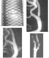
Rolling membrane Wallstent. Characteristics of the stent followed by illustration of three selected cases. A) Angle of the stent framework (same angle in the Carotid Easy Wallstent). Case 1. B) Ulcerated plaque involving both the internal and common carotid arteries before treatment. C) Control angiography after treatment. Case 2. D) Delayed auto-expansion of the stent. In this case, due to catheterization difficulties, no complementary post-dilatation was performed on this symptomatic ulcerated plaque. Immediate post-stent placement angiogram. E) 6 month follow-up angiogram. Significant auto-expansion of the stent The patient has not presented symptoms. Case 3. F) Symptomatic coiling of the internal carotid artery. Rare spontaneous secondary correction of the coiling after stenting. Immediate post-stent placement angiogram. G) 24 hour follow-up angiogram. Spontaneous correction of the coiling. H) One year follow-up angiogram. Persistent good pattern of the stent. The patient has remained asymptomatic.
Figure 8
Figure 8
Rolling membrane Wallstent. Characteristics of the stent followed by illustration of three selected cases. A) Angle of the stent framework (same angle in the Carotid Easy Wallstent). Case 1. B) Ulcerated plaque involving both the internal and common carotid arteries before treatment. C) Control angiography after treatment. Case 2. D) Delayed auto-expansion of the stent. In this case, due to catheterization difficulties, no complementary post-dilatation was performed on this symptomatic ulcerated plaque. Immediate post-stent placement angiogram. E) 6 month follow-up angiogram. Significant auto-expansion of the stent The patient has not presented symptoms. Case 3. F) Symptomatic coiling of the internal carotid artery. Rare spontaneous secondary correction of the coiling after stenting. Immediate post-stent placement angiogram. G) 24 hour follow-up angiogram. Spontaneous correction of the coiling. H) One year follow-up angiogram. Persistent good pattern of the stent. The patient has remained asymptomatic.
Figure 9
Figure 9
Easy Wallstent first generation. Characteristics of the stent followed by an illustrative case with an embolic complication that occurred 5 hours after the procedure. This complication was directly related to the insufficient radial force of this type of stent that was incompletely expanded. This presumably led to aggregation in the stent followed by intracerebral migration when the level of the anticoagulant decreased. A) Angle of the stent framework originally designed to reduce the shortening of the stent (see text). B) Embolic complication case. Pattern of the stent after deployment and complementary postangioplasty. AP projection. Insufficiently expanded stent surrounded by the calcified plaque. C) Same procedure. Left oblique angiogram. Insufficient expansion.
Figure 10
Figure 10
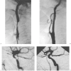
Easy Carotid Wallstent first generation. Transient hemorrhagic local complication. A) Symptomatic (transient stroke) right carotid stenosis. Pre-treatment angiogram. Very tortuous right internal carotid artery with a stenosis at its origin. B) Pattern of the stent framework before complementary angioplasty with incomplete expansion of the stent at the level of the calcified stenosis. C) Angiogram after complementary angioplasty. Late phase. Demonstration of a hemorrhage in and around the stent caused by a tear at the level of the calcifications that complementary angioplasty with a larger balloon was unable to stop. D) A Palmaz stent was placed in the Wallstent at the site of the bleeding, allowing for compression of the injured vessel wall structures thanks to the stronger radial force of this stent. E) Immediate control angiogram. Bleeding arrest and satisfactory pattern of the dilated vessel with correction of the vessel tortuosity.
Figure 10
Figure 10
Easy Carotid Wallstent first generation. Transient hemorrhagic local complication. A) Symptomatic (transient stroke) right carotid stenosis. Pre-treatment angiogram. Very tortuous right internal carotid artery with a stenosis at its origin. B) Pattern of the stent framework before complementary angioplasty with incomplete expansion of the stent at the level of the calcified stenosis. C) Angiogram after complementary angioplasty. Late phase. Demonstration of a hemorrhage in and around the stent caused by a tear at the level of the calcifications that complementary angioplasty with a larger balloon was unable to stop. D) A Palmaz stent was placed in the Wallstent at the site of the bleeding, allowing for compression of the injured vessel wall structures thanks to the stronger radial force of this stent. E) Immediate control angiogram. Bleeding arrest and satisfactory pattern of the dilated vessel with correction of the vessel tortuosity.
Figure 11
Figure 11
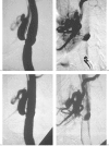
Embolic complications. Illustration of the anatomical and technical causes of residual embolic complications in the technique of protection with temporary occlusion of the internal carotid. As long as these causes are known they currently can easily be avoided. A) Example of the embolic material retrieved after cleaning of the working site. B) Schematic drawing illustrating two anatomical and two technical causes of unsatisfactory cerebral protection. Technical causes:1 - the stent is advanced in a narrow stenosis of the internal carotid before checking the efficacy of the balloon temporary occlusion without stent (see Figures 1C and 2B).This would give a wrong impression of occlusion on the pretreatment angiogram but after deployment of the stent a new angiogram, not always repeated, would show that the occlusion was related to the stent in narrow stenoses and not to the balloon, whose inflation might be insufficient to occlude the artery. 2 - The Percusurge balloon does not occlude the distal internal carotid efficiently. Anatomical causes: normal anatomical variations of large anastomoses between the external carotid and the vertebral and internal carotid arteries: l-meningo-ophthalmic artery; 2-muscular branches of the occipital and vertebral arteries. The absence of these large anastomoses should be checked before flushing the working site at the end of the procedure. C) Example of a complicated case : monocular blindness in a case of protected angioplasty in relation to flushing of particles in a meningo-ophthalmic artery. D) Unsatisfactory occlusions of the internal carotid artery with the Percusurge system that led us to develop another site of placement of the occlusive balloon (see figures 1 and 2) in the temporal carotid canal. Example l : the occlusive balloon inflated at its maximum diameter was not able to occlude the internal carotid. E) Example 2: late phase of a control angiogram performed after protected stenting of a carotid stenosis. This shows a filling of the internal carotid up to the occlusive balloon. This means that the occlusion is incomplete and that the potential risk of embolic migration remains around the very mobile Percusurge balloon when placed at this site.
Figure 12
Figure 12
Treatment in the same session of symptomatic tandem stenoses at the right carotid siphon and bifurcation (the left bifurcation was treated in a previous session). The protected treatment of the cervical internal carotid had already been performed. The carotid siphon stenosis was treated with an AVE stent (3.5 mm, 15 mm). A) Pretreatment angiogram. Stenosis of the internal carotid at the bifurcation predominant after the origin of the artery. B) Post-treatment angiogram. C) Pretreatment angiogram. Carotid siphon stenosis. D) Post-treatment angiogram. Correction of the stenosis.
Figure 13
Figure 13
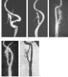
Long term follow-up. Excellent results to be confirmed illustrated by three selected patients. A) Ulcerated symptomatic stenosis with marked tortuosity of the internal carotid artery. B) One year follow-up angiogram. The patient has remained asymptomatic. Note the occlusion of the ulceration and the correction of the arterial tortuosity: by the stenting this is not a distal displacement and its mechanism could be explained by a kind of “regeneration” of the original tonicity of the arterial wall. C) Another patient. Bilateral carotid stenting. Two year follow-up angiogram. Right side. D) Same patient. Left side. Note a minor layer of myointimal hyperplasia. E) One year follow-up angiogram in a patient also presenting an associated fibromuscular dysplasia distal to the stent, more significant asymptomatic myointimal hyperplasia, (unfrequent case).
Figure 14
Figure 14
Cerebral digital parenchymography before and after stenting of a left internal carotid stenosis. Comparison of the late arterial phases. Parenchymography consists in the injection of a contrast medium bolus in the ascending aorta. AP head centering and modification of the digital windows (low and narrow) to enhance the information on the parenchymal vascular supply without eliminating the other arterial and venous information. A) Before stenting one notes the obvious asymmetry in the vascularization of the two hemispheres with hypovascularisation on the left side. On the left side there was also a marked delay at the early arterial phase and a venous stasis at the venous phase. B) immediate post-stenting parenchymography. Note the hypervascularization on the left side that we interpret as a sudden filling of the cortical vessels which were dilated before treatment to compensate for the relative hemispheric ischemia distal to the carotid stenosis. On the left side, there was no further delay at the early arterial phase and no more venous stasis at the venous phase.
Figure 15
Figure 15
Symptomatic ulceration without significant stenosis. Delayed closure. A) Angiogram before stenting, early phase : irregular posterior margin of the carotid bifurcation without significant stenosis. Stenosis of the external carotid. B) Same angiogram, late phase: the ulceration remains opacified. C) Angiogram immediately after stenting, early phase : the posterior margin of the carotid artery is slightly less irregular. D) Same angiogram, late phase: the ulceration appears slightly smaller. E) Six month follow-up angiogram, the patient has remained asymptomatic, early phase: the carotid margin appears smooth. There is some degree of circumferential myointimal hyperplasia or a special flow phenomenon on the proximal segment of the stent. The external carotid stenosis is unchanged. F) Same angiogram, late phase : the ulceration is no longer opacified.
Figure 15
Figure 15
Symptomatic ulceration without significant stenosis. Delayed closure. A) Angiogram before stenting, early phase : irregular posterior margin of the carotid bifurcation without significant stenosis. Stenosis of the external carotid. B) Same angiogram, late phase: the ulceration remains opacified. C) Angiogram immediately after stenting, early phase : the posterior margin of the carotid artery is slightly less irregular. D) Same angiogram, late phase: the ulceration appears slightly smaller. E) Six month follow-up angiogram, the patient has remained asymptomatic, early phase: the carotid margin appears smooth. There is some degree of circumferential myointimal hyperplasia or a special flow phenomenon on the proximal segment of the stent. The external carotid stenosis is unchanged. F) Same angiogram, late phase : the ulceration is no longer opacified.
Figure 16
Figure 16
Recent hemorrhagic complication that occurred a few hours after successful left carotid stenting. The patient was asymptomatic before the procedure but presented a modified left hemispheric area on the pretherapeutic MRI (presumed silent ischemic episodes). The hemorrhage occurred in this area. This case led us to consider not using Aspirin but only Clopidogrel in Carotid stenting (opinion to be confirmed). A) Pretherapeutic MRI. B) Post-stenting 6 hours CT.

Similar articles

Cited by

References

    1. Dotter CT, Judkins MP. Transluminal treatment of arteriosclerotic obstruction: description of a new technique and a preliminary report of its applications. Circulation. 1964;30:654–670. - PubMed
    1. Grüntzig A, Hopf H. Perkutane Rekanalisation chronischer arterieller Verschlüsse mit einem neuen Katheter: Modifikation der Dotter-technik. Deutsch Med Wochenschr. 1974;99:2502–2505. - PubMed
    1. Mathias K. Perkutane transluminale Katheterbe-handlung supraaortaler Arterienobstruktionen. Angiology. 1981;3:47–50.
    1. Theron J, Raymond J, et al. Percutaneous angioplasty of atheroclerotic and postsurgical stenosis of carotid arteries. Am J Neuroradiol. 1987;8:495–500. - PMC - PubMed
    1. Théron J, Courtheoux P, et al. New triple coaxial catheter for carotid angioplasty with cerebral protection. Am J Neuroradiol. 1990;11:869–874. - PMC - PubMed

LinkOut - more resources