

Junctioning longitudinally adjacent PTVs with Helical TomoTherapy
- PMID: 20592694
- PMCID: PMC5719944
- DOI: 10.1120/jacmp.v11i2.3047
Junctioning longitudinally adjacent PTVs with Helical TomoTherapy
Abstract
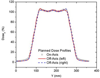
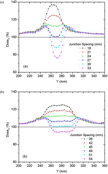
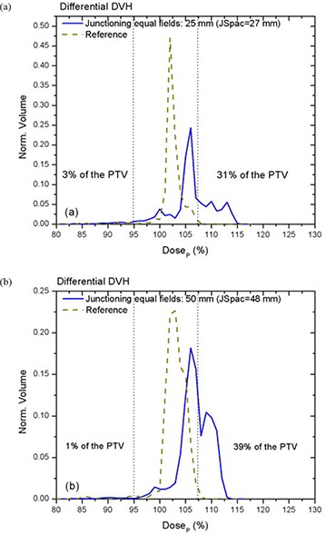
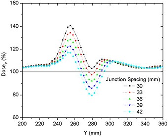
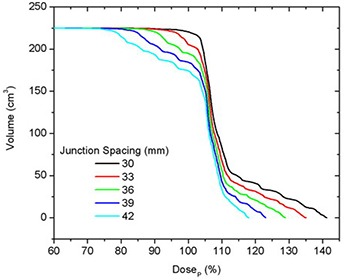
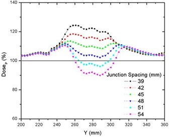
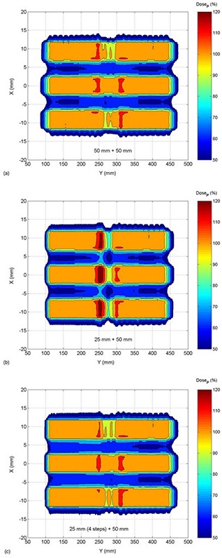
Irradiation of longitudinally adjacent PTVs with Helical TomoTherapy (HT) may be clinically necessary, for example in treating a recurrent PTV adjacent to a previously-treated volume. In this work, the parameters which influence the cumulative dose distribution resulting from treating longitudinally adjacent PTVs are examined, including field width, pitch, and PTV location. In-phantom dose distributions were calculated for various on- and off-axis cylindrical PTVs and were verified by ion chamber and film measurement. Dose distributions were calculated to cover 95% of the PTV by the prescribed dose (DP) using 25 and 50 mm long HT fields with pitches of either 0.3 or 0.45. These dose distributions where then used to calculate the 3D dose distribution in the junction region between two PTVs. The best junction uniformity was obtained for fields of equal width, with larger fields providing better intra-PTV dose homogeneity than smaller fields. Junctioning fields of different widths resulted in a much larger dose inhomogeneity, but this could be improved significantly by dividing the junction end of the PTV treated with the smaller field into multiple (up to 4) sub-PTVs, with the prescribed dose in each sub-PTV decreasing with proximity to the junction region. This provided a PTV matching with dose homogeneity similar to that achieved when junctioning two PTVs, both irradiated by the 50 mm field, and provided a distribution where 95% of the PTV received at least the prescribed dose, with maximum excursions from prescribed dose varying from -19% to +13%. We conclude that junctioning adjacent PTVs is possible. Treating longitudinally adjacent PTVs with different widths is a challenge, but dose uniformity is improved by breaking PTVs into multiple contiguous sub-PTVs modified to feather (broaden) the effective junctioning region.
Figures


Similar articles
-
The influence of different IMRT techniques on the peripheral dose: a comparison between sMLM-IMRT and helical tomotherapy.Strahlenther Onkol. 2009 Oct;185(10):696-702. doi: 10.1007/s00066-009-2005-9. Epub 2009 Oct 6. Strahlenther Onkol. 2009. PMID: 19806336
-
Sparing the penile bulb in the radical irradiation of clinically localised prostate carcinoma: A comparison between MRI and CT prostatic apex definition in 3DCRT, Linac-IMRT and Helical Tomotherapy.Radiother Oncol. 2009 Oct;93(1):57-63. doi: 10.1016/j.radonc.2009.04.004. Epub 2009 May 4. Radiother Oncol. 2009. PMID: 19410316
-
Dosimetric comparison of stereotactic body radiotherapy using 4D CT and multiphase CT images for treatment planning of lung cancer: evaluation of the impact on daily dose coverage.Radiother Oncol. 2009 Jun;91(3):314-24. doi: 10.1016/j.radonc.2008.11.018. Epub 2008 Dec 26. Radiother Oncol. 2009. PMID: 19111362 Clinical Trial.
-
Dosimetric comparison of helical tomotherapy, RapidArc, and a novel IMRT & Arc technique for esophageal carcinoma.Radiother Oncol. 2011 Dec;101(3):431-7. doi: 10.1016/j.radonc.2011.08.030. Epub 2011 Oct 1. Radiother Oncol. 2011. PMID: 21962823
-
Planning evaluation of radiotherapy for complex lung cancer cases using helical tomotherapy.Phys Med Biol. 2004 Aug 21;49(16):3675-90. doi: 10.1088/0031-9155/49/16/014. Phys Med Biol. 2004. PMID: 15446797
Cited by
-
MLC-based penumbra softener of EDW borders to reduce junction inhomogeneities.J Appl Clin Med Phys. 2017 May;18(3):118-129. doi: 10.1002/acm2.12082. Epub 2017 Apr 19. J Appl Clin Med Phys. 2017. PMID: 28422401 Free PMC article.
-
Feasibility of hybrid TomoHelical- and TomoDirect-based volumetric gradient matching technique for total body irradiation.Radiat Oncol. 2019 Dec 19;14(1):233. doi: 10.1186/s13014-019-1435-5. Radiat Oncol. 2019. PMID: 31856870 Free PMC article.
References
-
- Higgins PD, Han EY, Yuan JL, Hui S, Lee CK. Evaluation of surface and superficial dose for head and neck treatments using conventional or intensity‐modulated techniques. Phys Med Biol. 2007;52(4):1135–46. - PubMed
-
- Bauman G, Yartsev S, Rodrigues G, et al. A prospective evaluation of helical tomotherapy. Int J Radiat Oncol Biol Phys. 2007;68(2):632–41. - PubMed
-
- Bauman G, Yartsev S, Fisher B, et al. Simultaneous infield boost with helical tomotherapy for patients with 1 to 3 brain metastases. Am J Clin Oncol. 2007;30(1):38–44. - PubMed
-
- Baisden JM, Benedict SH, Sheng K, Read PW, Larner JM. Helical TomoTherapy in the treatment of central nervous system metastasis. Neurosurg Focus. 2007;22(3):E8. - PubMed
-
- Sheng K, Molloy JA, Read PW. Intensity‐modulated radiation therapy (IMRT) dosimetry of the head and neck: a comparison of treatment plans using linear accelerator‐based IMRT and helical tomotherapy. Int J Radiat Oncol Biol Phys. 2006;65(3):917–23. - PubMed
MeSH terms
LinkOut - more resources
Full Text Sources
