

Ensuring safety of implanted devices under MRI using reversed RF polarization
- PMID: 20593374
- PMCID: PMC3053145
- DOI: 10.1002/mrm.22468
Ensuring safety of implanted devices under MRI using reversed RF polarization
Abstract
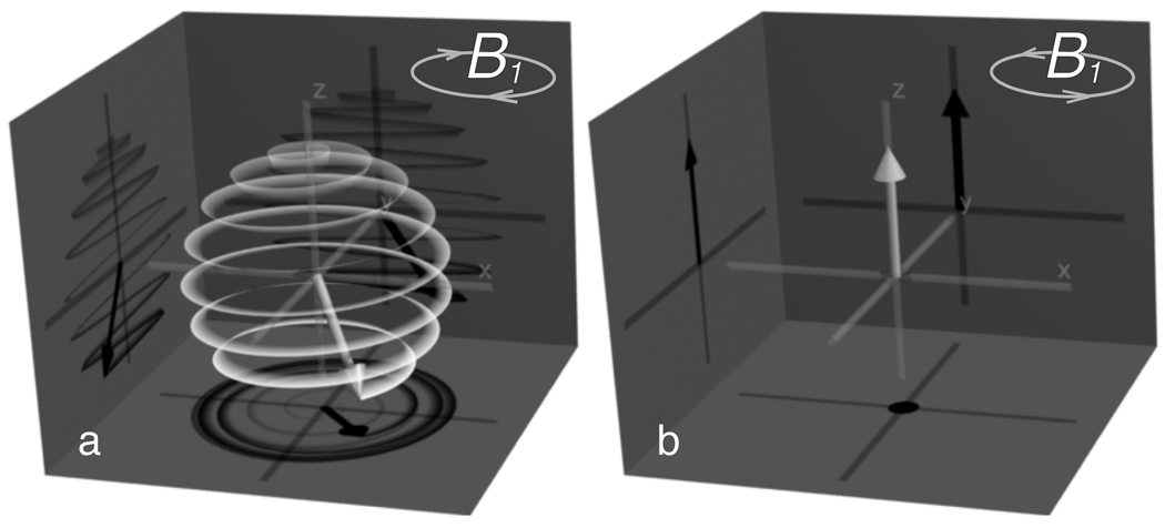
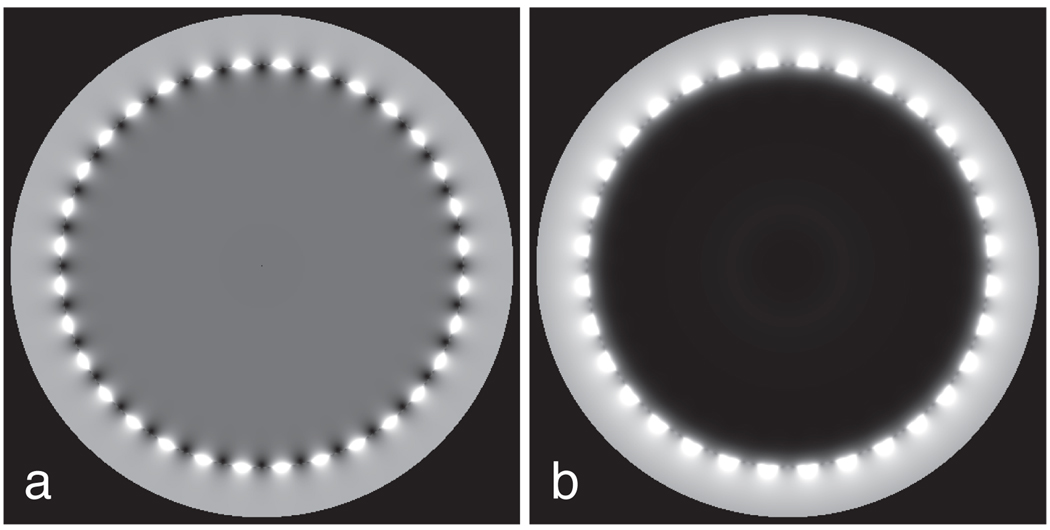
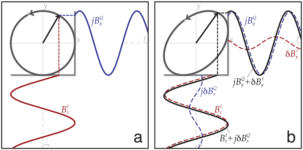
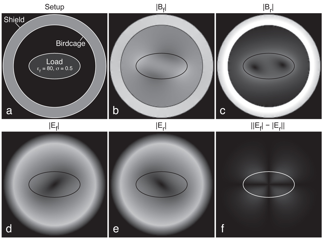
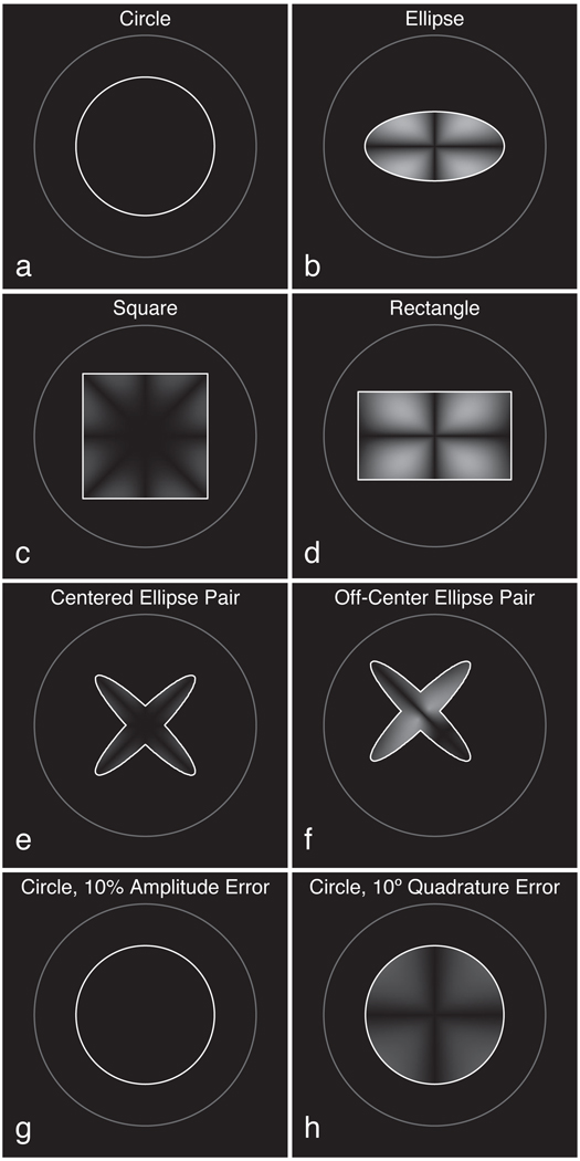
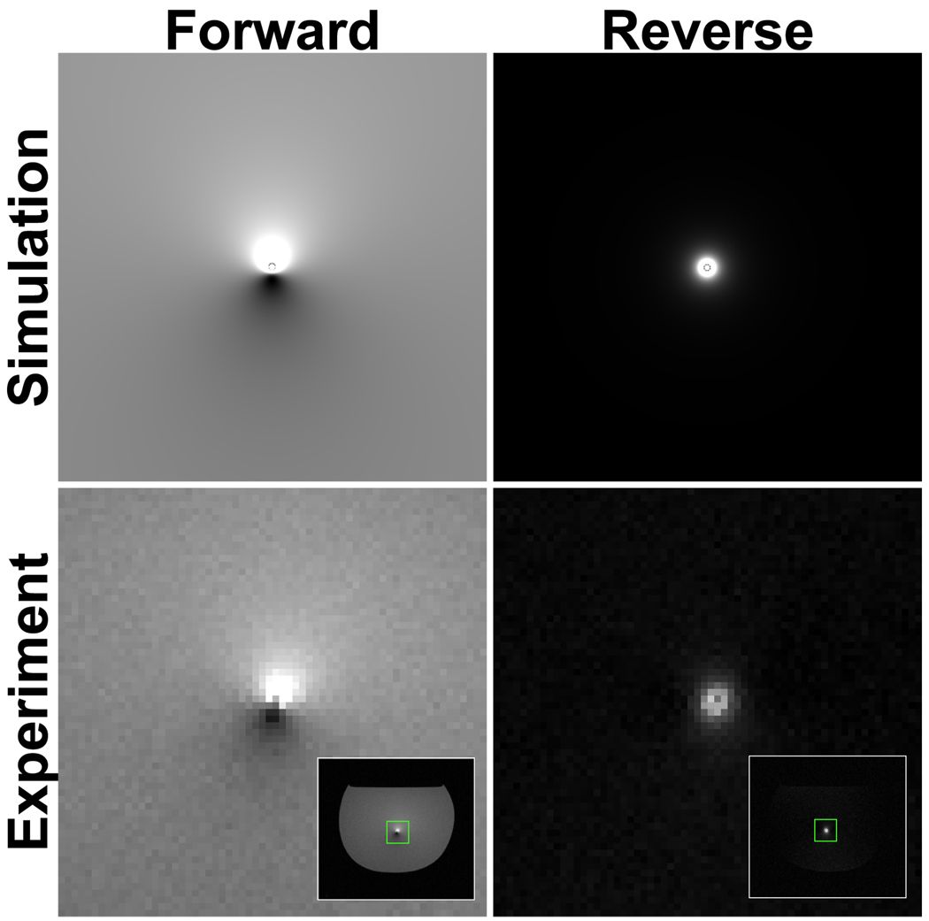
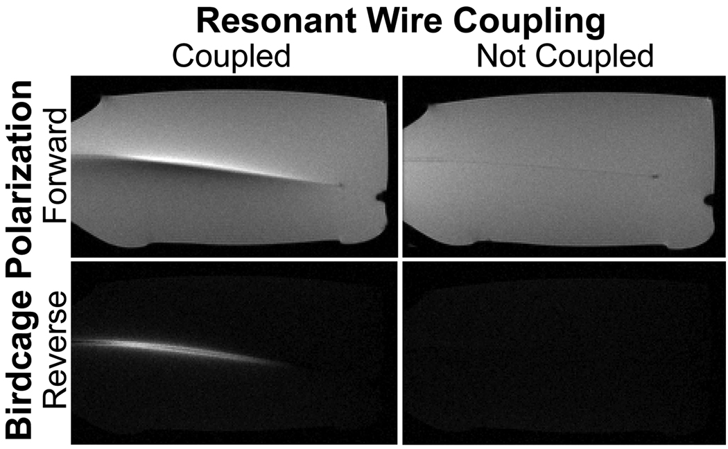
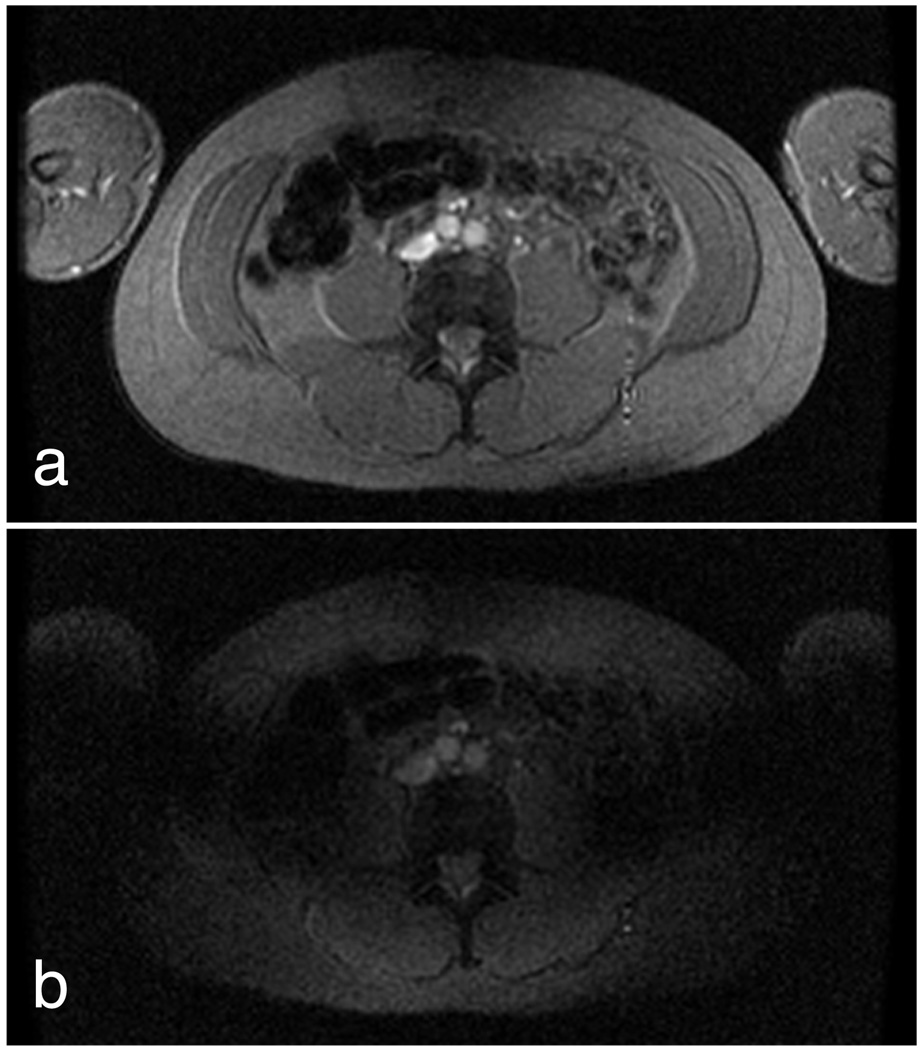
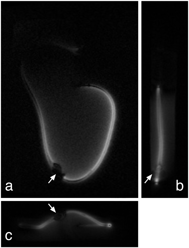
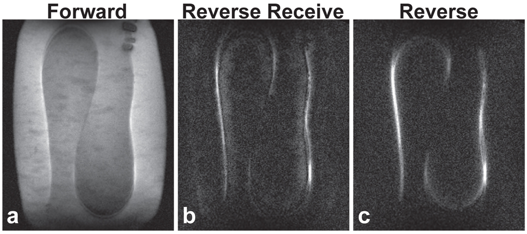
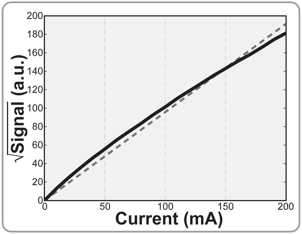
Patients with long-wire medical implants are currently prevented from undergoing magnetic resonance imaging (MRI) scans due to the risk of radio frequency (RF) heating. We have developed a simple technique for determining the heating potential for these implants using reversed radio frequency (RF) polarization. This technique could be used on a patient-to-patient basis as a part of the standard prescan procedure to ensure that the subject's device does not pose a heating risk. By using reversed quadrature polarization, the MR scan can be sensitized exclusively to the potentially dangerous currents in the device. Here, we derive the physical principles governing the technique and explore the primary sources of inaccuracy. These principles are verified through finite-difference simulations and through phantom scans of implant leads. These studies demonstrate the potential of the technique for sensitively detecting potentially dangerous coupling conditions before they can do any harm.
2010 Wiley-Liss, Inc.
Figures
Comment in
-
Comments on "Ensuring safety of implanted devices under MRI using reversed polarization".Magn Reson Med. 2011 Dec;66(6):1515-6; author reply 1517. doi: 10.1002/mrm.22992. Epub 2011 Oct 24. Magn Reson Med. 2011. PMID: 22025411 No abstract available.
Similar articles
-
Offline impedance measurements for detection and mitigation of dangerous implant interactions: an RF safety prescreen.Magn Reson Med. 2015 Mar;73(3):1328-39. doi: 10.1002/mrm.25202. Epub 2014 Mar 12. Magn Reson Med. 2015. PMID: 24623586 Free PMC article.
-
Comments on "Ensuring safety of implanted devices under MRI using reversed polarization".Magn Reson Med. 2011 Dec;66(6):1515-6; author reply 1517. doi: 10.1002/mrm.22992. Epub 2011 Oct 24. Magn Reson Med. 2011. PMID: 22025411 No abstract available.
-
Measuring RF-induced currents inside implants: Impact of device configuration on MRI safety of cardiac pacemaker leads.Magn Reson Med. 2009 Mar;61(3):570-8. doi: 10.1002/mrm.21881. Magn Reson Med. 2009. PMID: 19132759
-
Initial experience with magnetic resonance imaging-safe pacemakers : a review.J Interv Card Electrophysiol. 2011 Dec;32(3):213-9. doi: 10.1007/s10840-011-9610-0. Epub 2011 Oct 13. J Interv Card Electrophysiol. 2011. PMID: 21993594 Free PMC article. Review.
-
Mechanisms of electrode induced injury. Part 2: Clinical experience.Am J Electroneurodiagnostic Technol. 2007 Jun;47(2):93-113. Am J Electroneurodiagnostic Technol. 2007. PMID: 17679578 Review.
Cited by
-
Interventional device visualization with toroidal transceiver and optically coupled current sensor for radiofrequency safety monitoring.Magn Reson Med. 2015 Mar;73(3):1315-27. doi: 10.1002/mrm.25187. Epub 2014 Apr 1. Magn Reson Med. 2015. PMID: 24691876 Free PMC article.
-
Offline impedance measurements for detection and mitigation of dangerous implant interactions: an RF safety prescreen.Magn Reson Med. 2015 Mar;73(3):1328-39. doi: 10.1002/mrm.25202. Epub 2014 Mar 12. Magn Reson Med. 2015. PMID: 24623586 Free PMC article.
-
Deep learning-based local SAR prediction using B1 maps and structural MRI of the head for parallel transmission at 7 T.Magn Reson Med. 2023 Dec;90(6):2524-2538. doi: 10.1002/mrm.29797. Epub 2023 Jul 19. Magn Reson Med. 2023. PMID: 37466040 Free PMC article.
-
Modeling Endovascular MRI Coil Coupling With Transmit RF Excitation.IEEE Trans Biomed Eng. 2017 Jan;64(1):70-77. doi: 10.1109/TBME.2016.2538279. Epub 2016 Mar 4. IEEE Trans Biomed Eng. 2017. PMID: 26960218 Free PMC article.
-
Safe guidewire visualization using the modes of a PTx transmit array MR system.Magn Reson Med. 2020 Jun;83(6):2343-2355. doi: 10.1002/mrm.28069. Epub 2019 Nov 13. Magn Reson Med. 2020. PMID: 31722119 Free PMC article.
References
-
- Snow JS, Kalenderian D, Colasacco JA, Jadonath RL, Goldner BG, Cohen TJ. Implanted devices and electromagnetic interference: case presentations and review. J Invasive Cardiol. 1995;7:25–32. - PubMed
-
- Ahmed S, Shellock FG. Magnetic resonance imaging safety: implications for cardiovascular patients. J Cardiovasc Magn Reson. 2001;3:171–182. - PubMed
-
- Naehle CP, Meyer C, Thomas D, Remerie S, Krautmacher C, Litt H, Luechinger R, Fimmers R, Schild H, Sommer T. Safety of brain 3-T MR imaging with transmit-receive head coil in patients with cardiac pacemakers: pilot prospective study with 51 examinations. Radiology. 2008;249:991–1001. - PubMed
-
- Sommer T, Naehle CP, Yang A, Zeijlemaker V, Hackenbroch M, Schmiedel A, Meyer C, Strach K, Skowasch D, Vahlhaus C, Litt H, Schild H. Strategy for safe performance of extrathoracic magnetic resonance imaging at 1.5 tesla in the presence of cardiac pacemakers in non-pacemaker-dependent patients: a prospective study with 115 examinations. Circulation. 2006;114:1285–1292. - PubMed
-
- Nitz WR, Oppelt A, Renz W, Manke C, Lenhart M, Link J. On the heating of linear conductive structures as guide wires and catheters in interventional MRI. J Magn Reson Imaging. 2001;13:105–114. - PubMed
Publication types
MeSH terms
Grants and funding
LinkOut - more resources
Full Text Sources
Other Literature Sources
Medical
